A ground loop is essential to protect people from electric shock. For lightning protection, its own grounding device is created, which is not associated with the protective ground loop. For their correct construction, calculation is required.
The grounding device (GD) has a parameter called spreading resistance or simply resistance. It shows how good the current conductor is. For electrical installations with a line voltage of 380 V, the spreading resistance of the charger should not be more than 30 ohms, at transformer substations - 4 ohms. For ground loops of medical equipment and video surveillance equipment, server rooms, the rate is set individually and ranges from 0.5 to 1 Ohm.
The task of calculating a grounding device is to determine the number and location of vertical and horizontal ground electrodes sufficient to obtain the required resistance.
Determination of soil resistivity
The results of the calculations of the GD are significantly influenced by the characteristic of the soil at the place of its construction, called the resistivity (⍴). For each type of soil, there is a calculated value indicated in the table.
Soil resistance is influenced by humidity and temperature. In winter with maximum freezing and in summer during drought, the resistivity reaches its maximum values. To take into account the influence of weather conditions, corrections for the climatic zone are introduced to the value of ⍴.

If possible, the resistivity is measured before calculations.
Types of ground electrodes and calculation of their resistance
Earthing switches are natural and artificial, and both are used to create a grounding device. Calculate Impact natural earthing(reinforced concrete foundations, piles) by the amount of spreading resistance is difficult, it is easier to do it by measuring on the spot. The resistance of natural ground electrodes with a length of more than 100 m can be found in the table.

If the ⍴ value is different from 100 Ohm ∙ m, the R value is multiplied by the ⍴ / 100 ratio.
As artificial earthing fittings, pipes, angle or strip steel are used. The resistance of each of them is calculated according to its own formula indicated in the table.
Type of earthing switch | Calculation formula |
| Vertical electrode made of round reinforcing steel or pipe. The upper end is below ground level. | 
|
| Angle steel vertical electrode. Upper end below ground level | 
|
| The vertical electrode of a round reinforcing steel or pipe. Upper end above ground level | 
|
| Horizontal strip steel electrode | 
|
| Horizontal electrode made of round reinforcing steel or pipe | 
|
| Plate electrode (stacked vertically) | 
|
| Vertical electrode made of round reinforcing steel or angle steel | |
| Horizontal electrode made of round reinforcing steel or strip steel | 
|
Variable values in formulas:
Now the total resistance of the pins of artificial ground electrodes is calculated:


We calculate the resistance of the conductor connecting vertical ground electrodes according to the formula:

And the impedance of the grounding device.

If the calculated resistance of the ground loop turns out to be insufficient, we increase the number of vertical ground electrodes or change their appearance. We repeat the calculation until the required resistance value is obtained.
To ensure the safety of the operation of electrical equipment, the calculation of grounding devices is performed already at the design stage. Electrical installations with voltages up to 1000 V with an isolated neutral and a transformer power of more than 100 kVA must have a protective grounding resistance of not more than 4 ohms. With power
Rice. 1. Scheme of loop grounding of electrical equipment:
1 - electrical equipment; 2 - building; 3 - internal ground loop; 4, 5 - grounding conductors; 6 - grounding main conductor; 7 - ground electrode

Rice. 2. Scheme of remote focal grounding
electrical equipment:

Rice. 3. Scheme of remote grounding of electrical equipment with the arrangement of electrodes in a row:
1 - electrical equipment; 2 - building; 3 - internal ground loop; 4, 5 - grounding conductors; 6 - ground electrode
transformer less than 100 kVA, the grounding resistance should not exceed 10 ohms.
Resistance of ground electrodes to current spreading depends on their number, size, soil resistivity. The resistance of a single rod earthing (electrode) is determined by the formula, Ohm

 (1)
(1)
where ρ - soil resistivity, Ohm · m; d is the diameter of the rod earthing switch, m; l is the length of the grounding rod, m; h - depth of placement of the ground electrode, m
h = 0.5l + h 0, (2)
where h 0 is the distance from the soil surface to the beginning of a single ground electrode, from 0.5 to 0.8 m.
For ground electrodes made of angle steel, the equivalent diameter is preliminarily determined by the formula
where C is the width of the corner shelves, m.
The values of soil resistivity required for the calculation are given in table. 1.
Table 1
|
Soil type |
Oscillation limits values of specific soil resistance, Ohm m |
calculations specific soil resistance, Ohm m |
|
Loam | ||
|
Garden land | ||
|
Chernozem | ||
|
River water | ||
|
40000 – 45000 | ||
The number of rod ground electrodes required to achieve the standard resistance of the grounding device is determined by the formula

where R D - permissible (standard) grounding resistance, Ohm; η C - seasonality coefficient; η I - coefficient of use (shielding) in vertical ground electrodes.
Plugged electrodes are connected with a metal strip with a cross section of at least 48 mm 2. The length of the strip for the contour is
L n = 1.05a (N - 1), (5)
and when the electrodes are arranged in a row
where a is the distance between the electrodes, m; N is the number of electrodes, pcs.
The numerical values of the seasonality coefficient are mainly determined by fluctuations in soil moisture during the year and are given in table. 2.
table 2
|
Depth of placement (laying), m |
|||||
|
September | |||||
The numerical values of the utilization factor (shielding) for vertical ground electrodes (electrodes) when they are placed along the contour and in a row (remote diagram) are given in table. 3.
Table 3
|
ground electrodes |
The ratio of the distance between electrodes to their length |
|||||
|
placement in a row |
contour placement |
|||||
Resistance to spreading of electric current of a connecting strip laid in the ground is determined by the formula, Ohm

where L is the length of the strip, m; b - strip width, m; h is the depth of the strip from the earth's surface, m.
The resulting resistance to the spreading of electric current of the entire grounding device is determined by the formula

where η p is the utilization (shielding) factor of the horizontal connecting strip.
The numerical values of the utilization factor of the horizontal strip electrode, depending on the number of vertical electrodes connected by it, are given in table. 4.
Table 4
|
The ratio of the distance between vertical electrodes to their length |
Number of vertical electrodes |
||||||
|
placement in a row |
|||||||
|
contour placement |
|||||||
Grounding is necessary to ensure safety in the event of damage to electrical devices, insulation of power wiring, shorting of conductors. The essence of grounding is to reduce the potential at the point of contact with the grounded electrical installation to the maximum permissible values.
Potential reduction is performed in two ways:
- Zeroing - connection of the device body with a neutral conductor going to the substation;
- Grounding - Connects the chassis to a ground loop located in the ground outside the building.
The first option is easier, but in case of damage to the neutral conductor, it ceases to perform its functions, and this is dangerous. Therefore, the presence of a ground loop is a prerequisite for ensuring safety.
Calculation of grounding involves the determination of the resistance of the grounding device, which should not be more than specified by technical standards.
Ground loop
The design of the ground loop, the types of materials used are limited by the conditions that are contained in the documents, for example, in the PUE, the rules for electrical installations.
All electrical installations, without exception, must be grounded, both at the substation and at the enterprise or in everyday life.
The most common grounding loop design is one or more metal rods (earthing switches) buried in the ground and connected by a welded joint. A metal conductor is used to connect the ground loop to the devices to be grounded.

Unpainted steel or steel copper-clad materials are used as grounding conductors, the dimensions of which should not be less than those given below:
- Round rolled products - diameter not less than 12 mm;
- Corner - not less than 50x50x4 mm;
- Pipes - with a diameter of at least 25 mm with a wall thickness of at least 4 mm.
The better the conductivity of the ground electrodes, the more efficiently the grounding works, therefore the most preferable option is to use copper electrodes, but in practice this does not occur due to the high cost of copper.
Uncoated steel has a high corrosive capacity, especially at the interface between moist soil and air, therefore a minimum metal wall thickness (4 mm) has been determined.
Galvanized metal resists corrosion well, but not in the case of currents. Even the smallest current will trigger an electrochemical process, with the result that a thin layer of zinc will last a minimum of time.
Modern grounding systems are based on copper-plated steel. Since the amount of copper for manufacturing is not high, the cost of finished materials is not much higher than steel, and the service life increases many times over.

The most common designs of ground loops are triangular or in-line arrangement of electrodes. The distance between adjacent electrodes should be 1.2-2 m, and the depth of laying - 2-3 m. The depth of the laying (length of the electrodes) largely depends on the characteristics of the soil. The higher its electrical resistance, the deeper the electrodes should lie. In any case, this depth must exceed the depth of soil freezing, since frozen soil has a high ohmic resistance. The same applies to areas of land with low humidity.
Where it is possible for high currents to flow, for example, in a substation or an enterprise with powerful equipment, the approach to choosing the design of the ground loop and its calculation are very important for safety.
Grounding resistance factors
The calculation of a protective grounding device depends on many conditions, among which the main ones can be distinguished, which are used in further calculations:
- Soil resistance;
- Electrode material;
- Depth of insertion of electrodes;
- Location of ground electrodes relative to each other;
- Weather.
Soil resistance
The soil itself, with a few exceptions, has a low electrical conductivity. This characteristic changes depending on the moisture content, since water with dissolved salts in it is a good conductor. Thus, the electrical properties of the soil depend on the amount of moisture contained, the salt composition and the properties of the soil to retain moisture.

Common soil types and their characteristics
| Soil type | Resistivity ρ, Ohm m |
|---|---|
| Rock | 4000 |
| Loam | 100 |
| Chernozem | 30 |
| Sand | 500 |
| Sandy loam | 300 |
| Limestone | 2000 |
| Garden land | 50 |
| Clay | 70 |
The table shows that the resistivity can differ by several orders of magnitude. In real conditions, the situation is complicated by the fact that at different depths the type of soil can be different even without clearly defined boundaries between the layers.
Electrode material
This part of the calculations is the simplest, since only a few types of materials are used in the manufacture of grounding:
- Steel;
- Copper;
- Copper-plated steel;
- Cink Steel.
Copper in its pure form is not used due to its high cost, the most commonly used materials are pure and galvanized steel. Recently, more and more grounding systems have begun to be found, in which steel coated with a copper layer is used. Such electrodes have the lowest resistance, which has good stability over time, since the copper layer resists corrosion well.
Uncoated steel has the worst performance, since the corrosion layer (rust) increases the contact resistance at the electrode-soil interface.

Bookmark depth
The linear extent of the contact between the electrode and the ground and the size of the earth layer that participates in the current flow circuit depend on the depth of the electrode placement. The larger this layer, the lower the resistance value it will have.
On a note. In addition, when installing the electrodes, it should be borne in mind that the deeper they are located, the closer they will be to the aquifer.
Location of electrodes
This characteristic is the least obvious and difficult to understand. You should be aware that each grounding electrode has some effect on the neighboring ones, and the closer they are located, the less their effectiveness will be. The exact justification of the effect is rather complicated, it just needs to be taken into account in the calculations and construction.
It is easier to explain the dependence of efficiency on the number of electrodes. An analogy can be made here with resistors connected in parallel. The more there are, the lower the total resistance.

Weather
The grounding device has the best parameters at high soil moisture. In dry and frosty weather, the resistance of the soil increases sharply and upon reaching certain conditions (complete drying or freezing) takes on a maximum value.
Note! In order to minimize the influence of weather conditions, the electrode placement depth should be below the maximum freezing depth in winter or reach the aquifer to prevent drying out.
Important! Subsequent calculations must be performed for the worst operating conditions, since in all other cases the grounding resistance will decrease.
Calculation method
The main parameter of the calculation is the required value of the grounding resistance, which is regulated by regulatory documents, depending on the magnitude of the supply voltage, the type of electrical installations, and the conditions for their use.
There is no rigorous calculation of protective grounding that gives values for the number and length of electrodes, so it is performed based on some approximate data and tolerances.
To begin with, the type of soil is taken into account, and the approximate length of the grounding electrodes, their material and number are determined. Next, a calculation is performed, the order of which is as follows:
- The current spreading resistance for one electrode is determined;
- The number of vertical ground electrodes is calculated, taking into account their relative position.
Single earthing switch
We calculate the current spreading resistance according to the formula:
In this expression:
ρ - specific equivalent soil resistance;
l is the length of the electrode;
d is the diameter;
t is the distance from the earth's surface to the center of the electrode.
When using a corner instead of a pipe or rolled products, they take:
d = b · 0.95, where b is the width of the angle shelf.
Equivalent resistance of multilayer soil:
- ρ1 and ρ2 - resistivity of soil layers;
- H is the thickness of the upper layer;
- Ψ - seasonal coefficient.
The seasonal factor depends on the climatic zone. Also, it is amended, depending on the number of used electrodes. The indicative values of the seasonal coefficient are from 1.0 to 1.5.
Number of electrodes
The required number of electrodes is determined from the expression:
n = Rz / (K R), where:
- Rz - permissible maximum resistance of the grounding device;
- K is the utilization factor.
The utilization factor is selectable. in accordance with the selected number of ground electrodes, their relative position and the distance between them.
Row arrangement of electrodes
| Quantity electrodes | Coefficient | |
|---|---|---|
| 1 | 4 6 10 | 0,66-0,72 0,58-0,65 0,52-0,58 |
| 2 | 4 6 10 | 0,76-0,8 0,71-0,75 0,66-0,71 |
| 3 | 4 6 10 | 0,84-0,86 0,78-0,82 0,74-0,78 |
Contour placementelectrodes
| The ratio of the distance between electrodes to their length | Quantity electrodes | Coefficient |
|---|---|---|
| 1 | 4 6 10 | 0,84-0,87 0,76-0,80 0,67-0,72 |
| 2 | 4 6 10 | 0,90-0,92 0,85-0,88 0,79-0,83 |
| 3 | 4 6 10 | 0,93-0,95 0,90-0,92 0,85-0,88 |
The calculation of the ground loop does not always give the required value, therefore, it may need to be performed several times, changing the number and geometric dimensions of grounding electrodes.
Grounding measurement
Special measuring devices are used to measure the grounding resistance. The right to measure grounding is possessed by organizations with the appropriate permission. Usually these are energy organizations and laboratories. The measured parameters are entered into the measurement protocol and stored at the enterprise (in the workshop, at the substation).

Calculation of grounding resistance is a difficult task in which it is necessary to take into account many conditions, therefore it is more rational to use the help of organizations that specialize in this area. To solve the problem, you can make calculations on an online calculator, an example of which can be found on the Internet in the public domain. The calculator program itself will tell you what data should be taken into account in the calculations.
Video
A protective circuit created around any object that is supplied with electricity will ensure that high voltage flows into the ground through specially installed electrodes. Such designs protect expensive equipment from short circuits and burnout due to power surges. The installation of the structure must be carried out in accordance with the results of the calculations of the level of electrical conductivity of the conductors.
Purpose of calculation
Before installing on a residential or other facility, it is necessary to size it up. This design consists of:
- elements installed vertically to the surface of the earth;
- conductor;
- stripes connecting the contour in the horizontal plane.
The electrodes are dug in and connected to each other using a horizontal earthing switch. After that, the created protection system is connected to the electrical panel.
Such artificial structures are used in power networks with different voltage indicators:
- variable from 380 V;
- constant from 440 V;
at hazardous production facilities.

Protective systems are installed at different locations on the equipment. Depending on the place of installation, they can be remote or contoured. In open structures, the elements are connected directly to the grounding element. In outline devices, placement is along the outer perimeter or inside the device. For each type of protective installations, it is necessary to carry out a calculation in order to establish the resistance value of vertical ground electrodes, the number of required rods and the length of the strips for their connection.
In addition to special devices, natural systems can be used:
- communications from metal pipes;
- metal structures;
- substations;
- supports;
- metal sheath of the cable;
- casing.
Conductivity calculations are made for artificial structures. Arranging them at the place of use of power plants ensures the drainage of electric current into the ground, protecting people and equipment from large discharges as a result of a voltage surge. The lower the electrical conductivity, the lower the level of the strength of the electric current leaving through the protective structure.

Step-by-step calculation of the ground loop
Calculations should be carried out taking into account the number of elements, their distance from each other, soil conductivity and the depth of digging in the vertical ground electrode. Using these parameters, it will be possible to carry out an accurate calculation of the protective grounding.
First, you should use the table to determine the type of soil. Then select suitable materials for the construction. Then calculations are carried out according to special formulas that determine the number of all elements, as well as their ability to electrical conductivity.
Based on the results obtained, the entire system is installed, after which control measurements are carried out for its current conductivity.
Initial data
When calculating the strength value, the ratio of their number, the length of the connecting strips and the distance at which the digging is carried out should be made.

In addition, it will be necessary to take into account the specific resistance of the soil, which is determined by the level of its moisture. To achieve a stable value, it is necessary to bury the electrodes into the soil to a depth of at least 0.7 meters. It is also important not to deviate from the size of the protective device itself established by GOST. When carrying out the calculation, you need to use ready-made tables with already available indicators for the materials used and the electrical conductivity of certain types of soils.
Table of indicators of conductivity of various soils

The required depth to which the vertical electrode is buried in the ground is calculated by the formula:
When installing the protective structure, it is necessary to ensure that the metal rods completely enter the upper layer of the earth and partially into its lower levels. During the calculations, it will be necessary to use the average coefficients of the level of electrical conductivity of the soil in different seasons in certain climatic zones, presented in this table:
Soil resistance in different climatic zones

To accurately determine the number of vertical elements in the assembled structure, without taking into account the indicators for the narrow strips connecting them, you need to use the formula:
In it, Rn, denoting the strength of the current spreading over the soil of a certain type, the resistance coefficient for which is taken from the table.
To calculate the physical parameters of the material, the dimensions of the system elements used should be taken into account:
- for strips 12x4 - 48 mm2;
- at the corners 4x4 mm;
- for a steel circle - 10 mm2;
- for pipes with walls 3.5 mm thick.
Example of calculating grounding

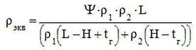
It is necessary to calculate the conductivity of the conductors used, taking into account the characteristics of the soil, for each electrode separately according to the formula:

Wherein:
- Ψ - climatic coefficient, which is taken from reference literature;
- ρ1, ρ2 - the value of the conductivity of the upper and lower layers of the earth;
- H is the thickness of the upper soil layer;
- t is the depth of the vertical element in the trench.
The rods for such structures are buried at a level of at least 0.7 meters, in accordance with the current regulations.
What should we have at the end of the calculation
After carrying out the calculations according to the formulas used, it is possible to obtain the exact resistance of the artificial-type grounding device. It is often impossible to measure these indicators in natural systems due to the impossibility of obtaining the exact standard sizes of buried communications, tracks, cables or already installed metal structures.

At the end of the calculations, it is possible to obtain the exact number of rods and strips for the contour, which will help create a reliable protection system for the equipment used and the entire facility as a whole. Calculations will also help to establish the exact length of the strips connecting the rods. The main result of all the calculations will be to obtain the final value of the properties of the conductors used in the created contour, which determines the strength of the electric current passing through them. This is the most important PES standard, which has certain values for networks with different voltage indicators.
Permissible values of grounding resistance, according to the standards
There are uniform standard values according to which the current spreading resistance for an electrical network with a certain voltage value should not exceed the established GOST standards. In networks with a voltage of 220 V, it should not be more than 8 ohms. At a voltage of 380 V, its value should be no higher than 4 ohms.

To calculate the indicators of the entire circuit, you can use the formula R = R0 / ηв * N, in which:
- R0 is the conductivity level for one electrode;
- R - indication of the level of obstruction of the passage of current for the entire system;
- ηv is the utilization factor of the protective device;
- N is the number of electrodes in the entire circuit.
Material required for the circuit device
You can assemble the contour from a metal material:
- corner,
- strips of specific sizes.
After that, it must be checked by an expert from an independent measuring laboratory. Structural reinforcement can be used as a natural contour when present in the supporting structures of a building. PES contains a special list of structures that can be used as a natural contour when creating protective systems.
To check the operation of the entire structure, it is necessary to check the total value and resistance of vertical earthing switches and the entire system with special devices. This work should be entrusted to independent experts from the electrical laboratory. In order for the structure to reliably protect the entire object, measurements should be carried out regularly, checking their value to the established standards.
Purpose of work: familiarize yourself with the algorithm for calculating protective grounding using the method of utilization rates of ground electrodes (electrodes) according to the permissible resistance of the grounding system to current spreading.
The purpose of the calculation: determination of the main parameters of grounding (the number, size and location of single vertical grounding conductors and horizontal grounding conductors)
1. Brief theoretical information.
Protective earth- deliberate electrical connection to earth or its equivalent of non-conductive metal parts that may be energized.
Purpose of protective grounding- elimination of the risk of injury to people by electric shock when voltage appears on the structural parts of electrical equipment, i.e. when closed to the case.
Functional principle of protective grounding- reduction to safe values of touch and step voltages caused by a short circuit to the case. This is achieved by reducing the potential of the grounded equipment, as well as equalizing the potentials by raising the potential of the foundation on which the person stands, to a potential close to the intended potential of the grounded equipment.
Grounding device is called a set of vertical grounding conductors - metal conductors in direct contact with the ground, and horizontal grounding conductors connecting the grounded parts of the electrical installation with the grounding conductor.
Indoors, potential equalization occurs naturally through metal structures, pipelines, cables and similar conductive objects connected to a branched grounding network.
Metal non-current-carrying parts of the equipment are subject to protective grounding, which, due to insulation failure, may be energized and which can be touched by people. At the same time, in a room with increased danger and especially dangerous due to the conditions of electric shock, as well as in outdoor installations, grounding is mandatory at a rated voltage of an electrical installation above 42V AC and above 110V DC, and in rooms without increased danger - at a voltage of 380V and above AC 440V and above DC. Only in hazardous areas, grounding is carried out regardless of the purpose of the installation.
Distinguish between ground electrodes artificial intended solely for grounding purposes, and natural- metal objects in the ground for other purposes (metal water pipes laid in the ground; pipes of artesian wells; metal frames of buildings and structures, etc.). It is forbidden to use pipelines of flammable liquids, combustible and explosive gases, as well as pipelines covered with insulation to protect against corrosion, as natural grounding conductors. Natural ground electrodes have, as a rule, low resistance to current spreading, and therefore their use for grounding purposes gives great savings. The disadvantages of natural ground electrodes are their availability and the possibility of disrupting the continuity of the connection of extended ground electrodes.
According to the form of arrangement of grounding electrodes, grounding can be contour and remote.
V outline grounding, all electrodes are located around the perimeter of the protected area. V remote(concentrated or focal) - earthing switches are located at a distance from each other not less than the length of the electrode.
In accordance with the requirements of mechanical strength and permissible heating by earth fault currents in installations with voltages above 1000V, the earthing steel main conductors must have a cross section of at least 120 mm 2, and in installations up to 1000V - at least 100 mm 2.
Additional information (extracts from the PUE - "Electrical Installation Rules", 2000) is given in Appendix 2.
2. Calculation procedure.
2.1 Determine the estimated short-circuit current by the formula:
I 3 = U l ∙ (35 l To + l v ) / 350, A, (1)
2.2 Calculate the required resistance of the grounding device R s in accordance with table. eleven . If R s more than the permissible value, then in further calculations R s take equal to the admissible value.
2.3 Determine the design soil resistivity ρ R :
ρ R = ρ rev ∙ , Ohm ∙ m (2)
where ρ rev- electrical resistivity of the soil, obtained by measurement or from reference literature (Table 2); - seasonality coefficient , the value of which depends on the climatic zone; (for the fourth climatic zone with average low temperatures in January from 0 to - 5 0 С and higher temperatures in July from +23 to +26 0 С = 1,3 ).
With a high resistivity of the earth, artificial reduction methods are used ρ rev in order to reduce the size and number of electrodes used and the area occupied by the ground electrode system. A significant result is achieved by chemical treatment of the area around ground electrodes using electrolytes, or by laying ground electrodes in pits with bulk coal, coke, and clay.