14.11.2016
one of the most successful SUVs in the world, its popularity is so great that legends are formed about it. The Land Cruiser has long ceased to be just a car; for many it is status and image. Depending on the generation of the Cruiser, you can roughly describe who its owner is and what he does. Due to the fact that the new 200th Kruzak is affordable only for wealthy people, many fans of the legendary SUV, in order to fulfill their dreams, are forced to buy a used Land Cruiser 200, but you will learn from this article.
A little history:
Model history Toyota Land Cruiser dates back more than 60 years. Land Cruiser 200 is the ninth generation of the legendary frame full-size SUV. The car debuted at the end of 2007 and continues to be produced to this day. Cruiser 200 is built on the same platform as " LexusLX 570", the design is also partially borrowed from this model, but the frame is borrowed from the second generation of the model " Toyota Tundra" For the Land Cruiser it was partially shortened, while its rigidity was increased by 20%. In 2002, a five-year program to develop the Land Cruiser 200 was launched, with prototype testing continuing from 2004 to 2007. Compared to previous versions, the roof pillars were significantly strengthened, which significantly increased safety when the vehicle overturned. In 2012, the car underwent restyling, during which the front optics were changed (LED strips of daytime running lights were added to it), rear and front bumpers, and radiator grille. In 2013, a new 4.6-liter engine (309 hp) was added; the peculiarity of this engine is that it has aluminum block, direct injection, phase shifters, and also, it is equipped with a variable length intake manifold. Some options, such as push-button start, a navigation system, a rearview camera and heated seats throughout the cabin, are included as standard.

Advantages and disadvantages of Toyota Land Cruiser 200 with mileage
When operating a Toyota Land Cruiser 200 in our latitudes, over time, some troubles may appear purely aesthetic character. So, in particular, chips and scratches appear on paint coating, and chrome elements quickly lose their original appearance. If the car is used in a metropolis, where the roads are liberally sprinkled with reagents, you need to monitor the condition of the frame, especially the place where the car’s Vin number is located. To prevent the frame from rusting, it should be generously treated with anti-corrosion agent every three years. Quite often the rear door lock switch fails.
Power units
Toyota Land Cruiser 200 is equipped with gasoline engines 4.0 (243 hp), 4.5 (265 hp), 4.6 (309, 319 hp), 4.7 (288 hp), 5.7 (381 hp). s.) and diesel 4.5 (235, 272 and 288 hp). The most popular among car enthusiasts is the 4.5 diesel engine; cars with a 4.6 petrol engine are much less common. The 5.7 engine is found only on cars imported from the USA, and the 4.0 is found from the Emirates. As operating experience has shown, the turbodiesel engine is quite reliable, but there are still minor complaints about it. Thus, on cars manufactured from 2008 to 2010, with a mileage of 100,000 km and above, oil consumption increased significantly, depending on the mileage, consumption is 200-500 grams per 1000 km. It would seem that the consumption is not so high, but the problem is that this engine has a normal waste consumption of up to 200 grams per 10,000 km. The reason for the increased oil appetite of the engine lies in a malfunction vacuum pump brake booster. With this malfunction, the pump forces air into the engine crankcase, which increases internal pressure, which contributes to increased oil consumption, including through the supercharger pipe. Replacing the vacuum pump will cost 600 USD. Because of Bad quality Diesel fuel owners have to change the fuel filter quite often, fortunately, a new filter is inexpensive - 30-50 USD. A common problem with both diesel and gasoline engines is a leak in the cooling system pump, which begins after 80-100 thousand kilometers. The cost of an original new pump is about 200 USD; for a non-original one they ask for about 100 USD. If this problem If not corrected in time, there is a high probability of engine overheating, which leads to expensive repairs of the power unit. 
Transmission
Toyota Land Cruiser 200 is equipped only with a six-speed automatic transmission. This transmission is very reliable, but some shortcomings were identified during operation. So, in particular, at a mileage of more than 100,000 km, owners encounter shocks and jerks when changing gears. The reason is the biting of the cardan shaft crosspieces, if the owner paid attention in time this disadvantage, then to solve it it was enough to syringe the cardan, if this no longer helped, the cardan had to be changed.
Salon
The interior of the Toyota Land Cruiser 200 is made of high-quality materials, but due to insufficiently high-quality assembly, crickets still appear in it. Most often, the glove compartment, headrests, rear seats and trunk are bothered by extraneous sounds. After 100,000 km, the heater motor begins to whistle, this is due to the fact that its bushings are worn out, a new motor will cost 300 USD. 
Driving performance of Toyota Land Cruiser 200 with mileage
Suspension- one of strong traits of this car, at the front it is independent, on two parallel arms on each side, at the rear there is a continuous axle with a Panhard rod. Controlled anti-roll bars equipped with hydraulic cylinders are installed at the front and rear. When driving off-road, the stabilizers become softer, resulting in improved cross-country ability, and on a flat road, the opposite is true, which improves handling and stability. The main suspension elements have a fairly long service life - about 200,000. weak points You can highlight the rear stabilizer struts and bushings, which last an average of 60-80 thousand km, and the front wheel bearings - up to 100,000 km.
One of the few weak points of the Toyota Land Cruiser 200 is the steering; a knock in the steering wheel can begin even after 40,000 km; in such cases, dealers change the entire steering column. Traditionally for this model, the braking system requires special attention; At each maintenance, it is necessary to lubricate the calipers, otherwise they will begin to sour. Also, you need to monitor the condition of the caliper piston boots, as they tear very often.
Result:
Toyota Land Cruiser 200 is a car for all occasions. The biggest advantage of this car is its reliability, and if you are looking for a car that very rarely needs to be repaired, then the 200 Cruiser is exactly what you need. Another plus of this car is that it slowly depreciates in the secondary market. Most importantly, before buying this car, be sure to check it on all possible bases for theft, since this model is considered one of the leaders in theft rate.
Advantages:
- Design.
- Acceleration dynamics.
- Off-road characteristics.
- Comfortable suspension.
- Spacious salon.
Flaws:
- Fuel consumption.
- Body swaying when maneuvering at speed.
- Quality of plastic in the cabin.
Toyota Land Cruiser
Description of Land Cruiser
Toyota Land Cruiser is a legendary SUV that has been produced for more than 60 years. The Land Cruiser is based on a frame body structure, dependent rear suspension and independent front suspension. According to tradition, there is high level comfort, off-road qualities, reliability and all these advantages together ensured the model serious popularity, even despite the high price tag. In the model range, the Toyota Land Cruiser stands higher and is also the flagship of Toyota, along with the simplified one.
Competitors include Range Rover, , Chevrolet Tahoe, Cadillac Escalade, /
and other large SUVs. By analogy with the Prado, based on the Toyota Land Cruiser, the luxury division of Toyota produces a model with almost the same appearance. In addition, it was also produced — modern version Land Cruiser J40.
Considering the weight (far beyond 2 tons) and huge dimensions, the engines on the Toyota Land Cruiser 100/200 are V8 with a displacement of 4.6 to 5.7 liters, for inexpensive versions there is a 4-liter V6, diesel only V8, on the Land Cruiser 100, together with V8, in-line sixes were also used, but they were abandoned in the new generation. Here you will find all the necessary descriptions of TLK motors, complete specifications, malfunctions, repairs, tuning, resource, oil and more.
The electronic engine control unit of Toyota 4A-FE, 5A-FE, 4A-GE, 7A-FE engines of Toyota Corolla, Crown, Toyota Carina E, Carib, Toyota Celica, Sprinter, Kaldina is programmed in such a way as to ensure optimal angle ignition timing at various engine operating modes.
Using information about engine operating conditions (rotation speed, coolant temperature, etc.), the microcomputer issues a command to supply a spark discharge exactly at the required moment in the engine operating cycle.
Fig.38. Layout of ignition system elements on a car with a 4A-FE engine (AT190)
1 - main fuse link 2.0L, 2 - spark plugs, 3 - electronic control unit (for models with left-hand drive steering), 4 - integrated ignition unit, 5 - diagnostic connector, 6 - electronic control unit (for models with right-hand drive), 7 - AM2 fuse-link (30 A).
The electronic engine control unit of Toyota 4A-FE, 5A-FE, 4A-GE, 7A-FE engines of Toyota Corolla, Corona, Toyota Carina E, Carib, Toyota Celica, Sprinter, Kaldina vehicles carries out current monitoring of its operating conditions using signals from the corresponding sensors
Using these signals, the electronic control unit calculates the required ignition timing and sends a control signal to the switch. The high voltage is distributed across the spark plugs according to the engine's firing order and causes a spark to occur between the spark plug electrodes, which ignites the air/fuel mixture.
The integrated ignition unit (unit) for Toyota engines 4A-FE, 5A-FE, 4A-GE, 7A-FE of Toyota Corolla, Corona, Toyota Carina E, Carib, Toyota Celica, Sprinter, Kaldina (non-contact ignition system unit) includes : switch, ignition coil, spark distributor for engine cylinders, as well as rotors and inductive coils of the crankshaft angle sensor and camshaft angle sensor.
The switch periodically interrupts the primary current coming from the electronic engine control unit (IGT signal), and thereby creates a spark discharge at the spark plugs. In addition, in order to increase the reliability of the ignition system, at the moment of sparking, information about this (IGF signal) is sent to the electronic engine control unit.
The ignition coil consists of a closed core, a primary winding that wraps around the core, and a secondary winding that wraps around the primary winding. This design allows you to create a high voltage that can cause a powerful spark discharge in the gap between the spark plug electrodes.
The ignition distributor distributes high voltage to the spark plugs of each cylinder in accordance with the firing order of the engine. The inductive coil "NE" with a magnetoelectric pulse generator allows you to determine the angular position of the crankshaft, and the inductive coil "G" - the angular position of the camshaft, which is necessary for the correct determination of the ignition timing.
Note: on some engines, for example 4A-GE (version without air mass meter) or 4A-FE (version with lean combustion system), two inductive coils “G1” and “G2” are used on the camshaft angle sensors.
Warnings for the ignition system in the operation of Toyota 4A-FE, 5A-FE, 4A-GE, 7A-FE engines:
Do not leave the ignition on for more than 10 minutes if the engine is not running.
When connecting the tachometer to the ignition system, connect the tachometer operating lead to the IG (-) terminal of the diagnostic connector of the integrated electronic ignition unit, and the power wires to the battery.
Since not all tachometers are compatible with this ignition system, before using the tachometer, make sure they are compatible.
Never allow the tachometer output contacts to touch ground: this will lead to failure of the switch and/or ignition coil of the engine being tested.
Do not disconnect the battery while the engine is running.
Make sure the switch is securely connected to vehicle ground.

Fig.39. Ignition system diagram 4A-FE and 7A-FE (AE102)
1 - battery, 2 - main fuse link (3.0W for AE or 2.0L for AT), 3 - fuse link AM2 (30 A), 4 - ignition switch, 5 - spark plugs, 6 - combined ignition unit, 7 - rotor and ignition distributor cap, 8 - capacitor, 9 and 10 - rotor and inductive winding of the crankshaft angle position sensor, 11 and 12 - rotor and inductive winding of the camshaft angle position sensor, 13 - ignition coil, 14 - switch, 15 - diagnostic connector of the switch, 16 - electronic control unit.

Fig.40. Diagram of the 4A-GE ignition system without air flow meter)
1 - battery, 2 - fuse link AM2 (30 A), 3 - ignition switch, 4 - spark plugs, 5 - rotor and ignition distributor cap, 6 - ignition coil, 7 - switch, 8 - to the tachometer, 9 and 10 - rotor and inductive winding of the crankshaft angle position sensor, 11 and 12 - rotor and inductive windings of the camshaft angle position sensor, 13 - electronic control unit.
Spark Check (For all engines except 4A-GE engine)
Disconnect the high voltage wires from the spark plugs.
Remove the spark plugs and reconnect the high-voltage wires to them.
Ground (connect to ground) the spark plug housings.
Make sure that when the engine is cranked by the starter, a spark occurs at each spark plug. (Only for 4A-GE and 4A-FE with lean combustion system)
Disconnect the high-voltage wires from the distributor.
Holding the ends of the wires at a distance of 12.5 mm from the ground (car body), make sure that there is sparking when the engine is cranked with the starter. Attention: to prevent a significant amount of fuel from entering the cylinders from operating injectors, the test should be carried out for no more than 1-2 s. If sparking is not observed, it is necessary to check the following:
sequences.
The terms “cold” and “hot” windings of the ignition coil or angle pulse sensor coil in the following sentences indicate the temperature of the windings:
- “cold” from -10°С to +50°С
- “hot” from +50°С to +100°С
Check the connections in the combined ignition unit: ignition coil, switch, distributor connectors.
Check the resistance of high voltage wires. Maximum resistance of each wire 25 kOhm
Check for voltage at the positive (+) terminal of the ignition coil with the ignition on.
Check the resistance of the ignition coil windings using the appropriate table.
Check the resistance of the inductive coil windings of the crankshaft angle sensor (terminals NE (+) and NE (-)) and the camshaft angle sensor (terminals G (+) and G (-)) according to the corresponding table.
If the resistance does not correspond to the technical data, then:
Engines 4A-FE (AE101 and AT190), 4A-GE and 5A-FE (AE110) - Replace the distributor housing assembly.
ICE 4A-FE (except AE101 and AT190) - Replace the complex (combined) ignition unit (contactless ignition system unit).
Check the distributor air gap. Gap size 0.2 - 0.4 mm
If the gap does not match the technical data, replace:
Engine 4A-FE (AE101 and AT190), 4A-GE, SAFE(AE110), 7A-FE(AE93, AE102)) - Distributor housing assembly.
Engine 4A-FE (except AE101 and AT190) - Combined ignition unit.
Check for the presence of a control signal from the electronic engine control unit.
Check the condition of the wiring from the computer to the integrated ignition unit. If necessary, replace the electronic control unit.
Try using a different switch.
Checking high-voltage wires of Toyota 4A-FE, 5A-FE, 4A-GE, 7A-FE engines of Toyota Corolla, Corona, Toyota Carina E, Carib, Toyota Celica, Sprinter, Kaldina cars
Disconnect the high-voltage wires from the spark plugs, holding them only by the rubber tips. Improper handling of wires may result in internal wire breaks.
Except 7A-FE and 4A-GE - Disconnect the high-voltage wires from the distributor cap or from the ignition unit cover. To do this, use a screwdriver to pull the spring latch and disconnect the holder along with the high-voltage wire from the distributor cover.
Using an ohmmeter, check the resistance of each high voltage wire.
For 7A-FE and 4A-GE engines, the wire resistance is checked together with the distributor cap or integrated electronic ignition unit. Maximum resistance...25 kOhm per wire. If the resistance exceeds the specified value, check the wire ends or replace the wires.
Except 7A-FE and 4A-GE - Connect the high-voltage wires to the distributor cap or integrated ignition unit.
Connect the high-voltage wires to the spark plugs, paying attention to the wiring and securing the wires with clamps.
Checking spark plugs for Toyota 4A-FE, 5A-FE, 4A-GE, 7A-FE engines
Disconnect the high voltage wires from the spark plugs.
Remove the spark plugs using a 16mm spark plug wrench.
Clean the spark plugs using a sandblaster or wire brush.
Visually check the condition of the spark plugs for wear on the electrodes, damage to the threads and/or insulators. Replace the spark plug if necessary.
Adjust the gap between the electrodes by bending only the side electrode.
Checking the elements of the ignition system or elements of the combined ignition unit of Toyota engines 4A-FE, 5A-FE, 4A-GE, 7A-FE of Toyota Corolla, Crown, Toyota Carina E, Carib, Toyota Celica, Sprinter, Kaldina cars
In the 4A-GE engine and in the 4A-FE engine (with a lean-burn combustion system) there is no integrated ignition unit, but the procedures for checking the same elements of the ignition system (ignition coil, distributor-distributor, switch, angular pulse sensors, etc.) are similar procedures for checking these elements in the combined ignition unit and are considered in parallel.
For ignition systems with a combined ignition unit - Disconnect the connectors of the integrated ignition unit, remove the distributor cap and rotor, and the ignition coil boot.
For engine ignition systems with a distributor - Disconnect the ignition coil connector and disconnect the high voltage wire from the ignition coil.
Checking the ignition coil of Toyota 4A-FE, 5A-FE, 4A-GE, 7A-FE engines
Attention: the terms “cold” and “hot” ignition coil windings in the following sentences indicate the temperature of the windings:
- “Cold” from -10°C to +50°C
- “Hot” from +50°C to +100°C
These definitions are further retained in relation to the inductive coils of angle pulse sensors.
Check the primary winding resistance using an ohmmeter connected to the ignition coil.
Check the secondary winding resistance using an ohmmeter connected to the ignition coil. If the resistance of any of the ignition coil windings is not within the specified value, replace the ignition coil.
For 4A-FE lean burn - Using a megger, measure the insulation resistance between the ignition coil positive (+) terminal and the high voltage wire terminal. The nominal resistance value is at least 10 MΩ. Otherwise, replace the ignition coil.
For 4A-FE with lean burn system - Connect the high voltage wire to the ignition coil as well as the ignition coil connector.
Checking the supply voltage of the integrated ignition unit (4A-FE (AE111), 7A-FE (AE115), 5A-FE (AE110)
Disconnect the connector of the integrated ignition unit and measure the voltage between terminal “1” of the unit connector and ground by turning the ignition key to the “ON” and “START” positions. Supply voltage..... 9 -14 V
Checking the ignition distributor of Toyota 4A-FE, 5A-FE, 4A-GE, 7A-FE engines
Disconnect the distributor connector, remove the distributor cap and the spark distributor rotor.
Using a feeler gauge, check the air gap between the rotor teeth of the angle pulse sensor and the protrusion of the inductive coil core of this sensor. If two angle sensors are used in the ignition system (crankshaft angle sensor "NE" and camshaft angle sensor "G1"), then similar measurements should be performed in each sensor.
On 4A-GE engines without an air mass meter, such measurements must be carried out three times: in the crankshaft angle sensor "NE" and two camshaft angle sensors "GT and G2". The nominal air gap is 0.2 - 0.4 mm. If the clearance is outside the specified limits, replace the distributor body, distributor assembly, or ignition assembly housing.
Using an ohmmeter, check the resistance of the inductive coils of the crankshaft and camshaft angle sensors.
____________________________________________________________________________
The most common and most widely repaired of Japanese engines is the (4,5,7)A-FE series engines. Even a novice mechanic or diagnostician knows about possible problems engines of this series. I will try to highlight (gather into a single whole) the problems of these engines. There are not many of them, but they cause a lot of trouble to their owners.

Sensors
Oxygen sensor - Lambda probe.
"Oxygen sensor" - used to fix oxygen in exhaust gases. Its role is invaluable in the fuel trim process. Read more about sensor problems in article.


Many owners seek diagnostics due to increased fuel consumption. One of the reasons is a simple break in the heater in the oxygen sensor. The error is recorded by the control unit with code number 21. The heater can be checked with a conventional tester on the sensor contacts (R- 14 Ohm). Fuel consumption increases due to the lack of fuel supply correction during warm-up. You will not be able to restore the heater - only replacing the sensor will help. The cost of a new sensor is high, and it makes no sense to install a used one (their service life is long, so it’s a lottery). In such a situation, as an alternative, you can install no less reliable universal sensors NTK, Bosch or original Denso.
 The quality of the sensors is not inferior to the original, and the price is significantly lower. The only problem may be correct connection sensor terminals. When the sensitivity of the sensor decreases, fuel consumption also increases (by 1-3 liters). The functionality of the sensor is checked with an oscilloscope on the diagnostic connector block, or directly on the sensor chip (number of switchings). Sensitivity decreases when the sensor is poisoned (contaminated) by combustion products.
Engine temperature sensor.
 The "temperature sensor" is used to record the temperature of the motor. If not proper operation The owner of the sensor will face a lot of problems. If the sensor's measuring element breaks, the control unit replaces the sensor readings and records its value at 80 degrees and records error 22. The engine, with such a malfunction, will operate in normal mode, but only while the engine is warm. As soon as the engine cools down, it will be difficult to start it without doping, due to the short opening time of the injectors. There are often cases when the resistance of the sensor changes chaotically when the engine is running at idle. – the revolutions will float. This defect can be easily recorded on the scanner by observing the temperature reading. On a warm engine it should be stable and not change randomly from 20 to 100 degrees.
 With such a defect in the sensor, a “black acrid exhaust” is possible and unstable operation on the H.H. and, as a result, increased consumption, as well as the inability to start a warm engine. You can start the engine only after standing for 10 minutes. If you are not completely confident in the correct operation of the sensor, its readings can be replaced by connecting a 1-kohm variable resistor or a constant 300-ohm resistor into its circuit for further verification. By changing the sensor readings, the change in speed at different temperatures is easily controlled.
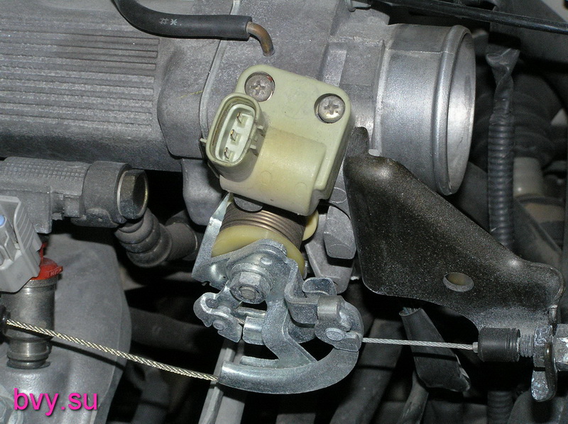
Throttle position sensor.
Position sensor throttle valve Shows the on-board computer what position the throttle is in.


Quite a few cars went through the assembly and disassembly procedure. These are the so-called “designers”. When removing the engine in field conditions and subsequent assembly, the sensors on which the engine is often leaned suffered. If the TPS sensor breaks, the engine stops throttling normally. The engine choke when revving up. The automatic shifts incorrectly. The control unit records error 41. When replacing, the new sensor must be configured so that the control unit correctly sees the sign of Х.Х. when the gas pedal is fully released (the throttle valve is closed). In the absence of the idling sign, there will be no adequate regulation of the idle speed, and there will be no forced idling mode when braking the engine, which again will entail increased fuel consumption. On 4A, 7A engines, the sensor does not require adjustment; it is installed without the possibility of rotation and adjustment. However, in practice there are often cases of bending of the petal, which moves the sensor core. In this case, there is no sign of x/x. Adjustment of the correct position can be done using a tester without using a scanner - based on idle speed.
THROTTLE POSITION……0%
IDLE SIGNAL……………….ON
MAP absolute pressure sensor
The pressure sensor shows the computer the actual vacuum in the manifold; based on its readings, the composition of the fuel mixture is formed.


This sensor is the most reliable of all installed on Japanese cars. His reliability is simply amazing. But it also has its fair share of problems, mainly due to improper assembly. They either break the receiving “nipple” and then seal any passage of air with glue, or break the tightness of the supply tube. With such a break, fuel consumption increases, the level of CO in the exhaust increases sharply to 3%. It is very easy to observe the operation of the sensor using a scanner. The INTAKE MANIFOLD line shows the vacuum in the intake manifold, which is measured by the MAP sensor. If the wiring is broken, the ECU registers error 31. In this case, the opening time of the injectors sharply increases to 3.5-5ms. When changing the throttle, a black exhaust appears, the spark plugs are seated, and shaking appears at idle. and stopping the engine.
Knock sensor.
The sensor is installed to register detonation knocks (explosions) and indirectly serves as a “corrector” for the ignition timing.


The recording element of the sensor is a piezoelectric plate. If the sensor malfunctions, or the wiring is broken, at revs over 3.5-4 tons, the ECU records error 52. Sluggishness is observed during acceleration. You can check the functionality with an oscilloscope, or by measuring the resistance between the sensor terminal and the housing (if there is resistance, the sensor requires replacement).
Crankshaft sensor.
The crankshaft sensor generates pulses from which the computer calculates the rotation speed of the engine crankshaft. This is the main sensor by which all engine operation is synchronized.


7A series engines have a crankshaft sensor. A conventional inductive sensor is similar to the ABC sensor and is practically trouble-free in operation. But embarrassments also happen. When an interturn short circuit occurs inside the winding, the generation of pulses is disrupted at certain speeds. This manifests itself as a limitation of engine speed in the range of 3.5-4 rpm. A kind of cut-off, only at low revs. Detecting an interturn short circuit is quite difficult. The oscilloscope does not show a decrease in pulse amplitude or a change in frequency (during acceleration), and it is quite difficult to notice changes in Ohm fractions with a tester. If symptoms of rev limiting occur at 3-4 thousand, simply replace the sensor with a known good one. In addition, a lot of trouble is caused by damage to the drive ring, which is broken by mechanics when replacing the front crankshaft oil seal or timing belt. By breaking the teeth of the crown and restoring them by welding, they achieve only a visible absence of damage. In this case, the crankshaft position sensor ceases to adequately read information, the ignition timing begins to change chaotically, which leads to loss of power, unstable engine operation and increased fuel consumption.
Injectors (nozzles).
Injectors are solenoid valves, which inject fuel under pressure into the engine intake manifold. The engine computer controls the operation of the injectors.


Over many years of operation, the nozzles and needles of the injectors become covered with resins and gasoline dust. All this naturally disrupts the correct spray pattern and reduces the performance of the nozzle. With severe contamination, noticeable engine shaking is observed and fuel consumption increases. It is possible to determine clogging by conducting a gas analysis; based on the oxygen readings in the exhaust, one can judge whether the filling is correct. A reading above one percent will indicate the need to flush the injectors (if correct installation timing and normal fuel pressure). Either by installing the injectors on a stand and checking the performance in tests, in comparison with a new injector. Nozzles are washed very effectively by Laurel, Vince, both in CIP installations and in ultrasound.
Idle air valve.IAC
The valve is responsible for engine speed in all modes (warm-up, idling, load).


During operation, the valve petal becomes dirty and the stem becomes jammed. The revolutions hang during warm-up or at idle (due to the wedge). There are no tests for changes in speed in scanners when diagnosing this motor. You can evaluate the performance of the valve by changing the readings of the temperature sensor. Put the engine into “cold” mode. Or, after removing the winding from the valve, twist the valve magnet with your hands. The jamming and wedge will be noticeable immediately. If it is impossible to easily dismantle the valve winding (for example, on the GE series), you can check its functionality by connecting to one of the control terminals and measuring the duty cycle of the pulses, while simultaneously monitoring the idle speed. and changing the load on the engine. On a fully warmed-up engine, the duty cycle is approximately 40%; by changing the load (including electrical consumers), you can estimate an adequate increase in speed in response to a change in duty cycle. When the valve is mechanically jammed, there is a smooth increase in the duty cycle, which does not entail a change in the rotation speed. You can restore operation by cleaning off carbon deposits and dirt with a carburetor cleaner with the windings removed. Further adjustment of the valve consists of setting the idle speed. On a fully warmed-up engine, by rotating the windings on the mounting bolts, achieve the table speed for this type of car (according to the tag on the hood). Having previously installed the jumper E1-TE1 in the diagnostic block. On “younger” 4A, 7A engines the valve was changed. Instead of the usual two windings, a microcircuit was installed in the body of the valve winding. We changed the valve power supply and the color of the plastic winding (black). It is already pointless to measure the resistance of the windings at the terminals. Power and control signal are supplied to the valve rectangular shape variable duty cycle. To make it impossible to remove the winding, non-standard fasteners were installed. But the problem of the rod wedge remained. Now if you clean with a regular cleaner, the grease is washed out of the bearings (the further result is predictable, the same wedge, but because of the bearing). You should completely remove the valve from the throttle valve block and then carefully wash the stem and petal.
Ignition system. Candles.


A very large percentage of cars come to service with problems in the ignition system. When operating on low-quality gasoline, the spark plugs are the first to suffer. They become covered with a red coating (ferrosis). There will be no high-quality spark formation with such spark plugs. The engine will run intermittently, with misfires, fuel consumption increases, and the level of CO in the exhaust rises. Sandblasting cannot clean such candles. Only chemistry (lasts for a couple of hours) or replacement will help. Another problem is increased clearance (simple wear). Drying of the rubber tips of high-voltage wires and water entering during engine washing provoke the formation of a conductive path on the rubber tips.


Because of them, sparking will not be inside the cylinder, but outside it. With smooth throttling, the engine runs stably, but with sharp throttling, it breaks up. In this situation, it is necessary to replace both the spark plugs and the wires at the same time. But sometimes (in field conditions) if replacement is impossible, you can solve the problem with an ordinary knife and a piece of sandstone (fine fraction). Use a knife to cut off the conductive path in the wire, and use a stone to remove the strip from the ceramic of the candle. It should be noted that you cannot remove the rubber band from the wire, this will lead to complete inoperability of the cylinder.
Another problem is related to the incorrect procedure for replacing spark plugs. The wires are pulled out of the wells with force, tearing off the metal tip of the rein. With such a wire, misfires and floating speed are observed. When diagnosing the ignition system, you should always check the performance of the ignition coil on a high-voltage spark gap. The simplest check is to look at the spark at the spark gap with the engine running.

If the spark disappears or becomes thread-like, this indicates an interturn short circuit in the coil or a problem in the high-voltage wires. Wire breakage is checked with a resistance tester. A small wire is 2-3k, then a longer wire is 10-12k. The resistance of a closed coil can also be checked with a tester. The resistance of the secondary winding of the broken coil will be less than 12k.


The next generation (remote) coils do not suffer from such ailments (4A.7A), their failure is minimal. Proper cooling and wire thickness eliminated this problem.


Another problem is the leaking seal in the distributor. Oil getting on the sensors corrodes the insulation. And when exposed to high voltage, the slider oxidizes (becomes covered with a green coating). The coal turns sour. All this leads to a breakdown in spark formation. While driving, chaotic shooting (into the intake manifold, into the muffler) and crushing are observed.
Subtle faults
On modern 4A, 7A engines, the Japanese changed the firmware of the control unit (apparently to warm up the engine faster). The change is that the engine reaches idle speed only at a temperature of 85 degrees. The design of the engine cooling system was also changed. Now a small cooling circle intensively passes through the head of the block (not through the pipe behind the engine, as was before). Of course, the cooling of the head has become more efficient, and the engine as a whole has become more efficient in cooling. But in winter, with such cooling, when driving, the engine temperature reaches 75-80 degrees. And as a result, constant warm-up speeds (1100-1300), increased fuel consumption and nervousness of the owners. You can combat this problem by either insulating the engine more, or by changing the resistance of the temperature sensor (by deceiving the ECU), or by replacing the thermostat for the winter with a higher opening temperature.
Oil
Owners pour oil into the engine indiscriminately, without thinking about the consequences. Few people understand that Various types oils are incompatible and when mixed they form an insoluble mess (coke), which leads to complete destruction of the engine.


All this plasticine cannot be washed off with chemicals, it can only be cleaned mechanically. It should be understood that if it is unknown what type of old oil is, then you should use flushing before changing. And one more piece of advice for owners. Pay attention to the color of the dipstick handle. He yellow color. If the color of the oil in your engine is darker than the color of the handle, it’s time to change it, rather than wait for the virtual mileage recommended by the engine oil manufacturer.
Air filter.
 The most inexpensive and easily accessible element is the air filter. Owners very often forget about replacing it, without thinking about the likely increase in fuel consumption. Often, due to a clogged filter, the combustion chamber becomes very dirty with burnt oil deposits, valves and spark plugs become very dirty. When diagnosing, one may mistakenly assume that the wear of the valve stem seals is to blame, but the root cause is a clogged air filter, which increases the vacuum in the intake manifold when dirty. Of course, in this case the caps will also have to be changed.
Some owners don’t even notice that they live in the building air filter garage rodents. Which speaks volumes about their complete disregard for the car.


The fuel filter also deserves attention. If it is not replaced in time (15-20 thousand mileage), the pump begins to work with overload, the pressure drops, and as a result, the need to replace the pump arises. Plastic parts of pump impeller and check valve wear out prematurely.


The pressure drops. It should be noted that the motor can operate at a pressure of up to 1.5 kg (with a standard pressure of 2.4-2.7 kg). With reduced pressure, constant shooting into the intake manifold is observed; starting is problematic (afterwards). Traction is noticeably reduced. It is correct to check the pressure with a pressure gauge (access to the filter is not difficult). In field conditions, you can use the “return flow test”. If, when the engine is running, less than one liter of gasoline flows out of the return hose in 30 seconds, we can judge that the pressure is low. You can use an ammeter to indirectly determine the pump's performance. If the current consumed by the pump is less than 4 amperes, then the pressure is lost. You can measure the current on the diagnostic block.  When using a modern tool, the filter replacement process takes no more than half an hour. Previously, this took a lot of time. Mechanics always hoped that they would be lucky and the lower fitting would not rust. But this is often what happened. I had to rack my brains for a long time about which gas wrench to use to hook the rolled-up nut of the lower fitting. And sometimes the process of replacing the filter turned into a “movie show” with the removal of the tube leading to the filter. Today no one is afraid to make this replacement.
Control block.
Until the year 1998, control units did not have serious problems during operation. The units had to be repaired only due to severe polarity reversal. It is important to note that all terminals of the control unit are signed. It is easy to find on the board the required sensor output for checking or checking the wire continuity. The parts are reliable and stable in operation at low temperatures.


In conclusion, I would like to dwell a little on gas distribution. Many “hands-on” owners perform the belt replacement procedure on their own (although this is not correct, they cannot tighten the crankshaft pulley correctly). Mechanics make a high-quality replacement within two hours (maximum). If the belt breaks, the valves do not meet the piston and fatal destruction of the engine does not occur. Everything is calculated down to the smallest detail.
We tried to talk about the most frequently occurring problems on engines of this series. The engine is very simple and reliable and subject to very harsh operation on “water-iron gasoline” and dusty roads of our great and mighty Motherland and the “maybe” mentality of the owners. Having endured all the bullying, it continues to delight to this day with its reliable and stable operation, having won the status of the most reliable Japanese engine.
Vladimir Bekrenev, Khabarovsk.
Andrey Fedorov, Novosibirsk.
- Back
- Forward
Only registered users can add comments. You do not have permission to leave comments.
In 1987, the Japanese auto giant Toyota began producing a new series of engines for passenger cars, which was called “5A”. Production of the series continued until 1999. The Toyota 5A engine was produced in three modifications: 5A-F, 5A-FE, 5A-FHE.
The new 5A-FE engine had a gas distribution mechanism that provided 4 valves per cylinder, according to the DOHC design, that is, an engine equipped with two camshafts in a Double OverHead Camshaft, where each camshaft drives its own bank of valves. With this arrangement, one camshaft drives two intake valves, the other drives two exhaust valves. The valves are usually driven by pushers. The DOHC circuit in Toyota 5A series engines has made it possible to significantly increase their power.
Second generation Toyota 5A series engines
ATTENTION! A completely simple way to reduce fuel consumption has been found! Don't believe me? An auto mechanic with 15 years of experience also didn’t believe it until he tried it. And now he saves 35,000 rubles a year on gasoline!
An improved version of the 5A-F engine was the second generation 5A-FE engine. Toyota designers worked hard to improve the fuel injection system; as a result, the updated version of the 5A-FE was equipped with an electronic fuel injection system EFI - Electronic Fuel Injection.
| Volume | 1.5 l. |
| Power | 100 hp |
| Torque | 138 N*m at 4400 rpm |
| Cylinder diameter | 78.7 mm |
| Piston stroke | 77 mm |
| Cylinder block | cast iron |
| Cylinder head | aluminum |
| Gas distribution system | DOHC |
| Fuel type | petrol |
| Predecessor | 3A |
| Successor | 1NZ |
The engines of the Toyota 5A-FE modification were equipped with cars of classes “C” and “D”:
| Model | Body | Of the year | A country |
|---|---|---|---|
| Carina | AT170 | 1990–1992 | Japan |
| Carina | AT192 | 1992–1996 | Japan |
| Carina | AT212 | 1996–2001 | Japan |
| Corolla | AE91 | 1989–1992 | Japan |
| Corolla | AE100 | 1991–2001 | Japan |
| Corolla | AE110 | 1995–2000 | Japan |
| Corolla Ceres | AE100 | 1992–1998 | Japan |
| Corona | AT170 | 1989–1992 | Japan |
| Soluna | AL50 | 1996–2003 | Asia |
| Sprinter | AE91 | 1989–1992 | Japan |
| Sprinter | AE100 | 1991–1995 | Japan |
| Sprinter | AE110 | 1995–2000 | Japan |
| Sprinter Marino | AE100 | 1992–1998 | Japan |
| Vios | AXP42 | 2002–2006 | China |
If we talk about the quality of the design, it is difficult to find a more successful motor. At the same time, the engine is very repairable and does not cause car owners difficulties in purchasing spare parts. The Japanese-Chinese joint venture between Toyota and Tianjin FAW Xiali in China still produces this engine for its Vela and Weizhi small cars.
Japanese engines in Russian conditions
5A-FE under the hood of Toyota Sprinter
In Russia, Toyota car owners different models with 5A-FE modification engines give a generally positive assessment performance characteristics 5A-FE. According to them, the 5A-FE resource is up to 300 thousand km. mileage With further operation, problems with oil consumption begin. should be replaced at a mileage of 200 thousand km, after which replacement should be made every 100 thousand km.
Many owners of Toyotas with 5A-FE engines are faced with a problem that manifests itself in the form of noticeable dips at medium engine speeds. This phenomenon, according to experts, is caused either by low-quality Russian fuel or problems in the power supply and ignition system.
Subtleties of repair and purchase of a contract motor
Also, during the operation of 5A-FE motors, minor shortcomings are revealed:
- the engine is prone to high wear of camshaft beds;
- fixed piston pins;
- Difficulties sometimes arise with adjusting the clearances in the intake valves.
However, major renovation 5A-FE is quite rare.
If it is necessary to replace the entire motor, Russian market Today you can easily find a contract 5A-FE engine in very good condition and at an affordable price. It is worth clarifying that engines that have not been used in Russia are usually called contract engines. Speaking about Japanese contract engines, it should be noted that most of them have low mileage and meet all the manufacturer’s requirements regarding Maintenance. Japan has long been considered the world leader in the speed of innovation model range cars. Thus, a lot of cars end up at car wreckers there, the engines of which have a fair amount of service life.