Modern human life absolutely cannot be comfortable without electricity. When it is absent, it seems that life has stopped, because any Appliances or electric tool requires an electrical connection. Sometimes without electricity it will not even be possible to cook food, not to mention the normal lighting of the home. Therefore, if you are thinking of construction, then the wiring diagram in a private house should be a priority issue that should be given special attention. It is necessary to think over and calculate everything to the smallest detail, so that no slightest mistake or inaccuracy in the laying and connection of the electrical network will lead to a breakdown of household appliances in the future, or, even worse, to a fire and fire.
What is the need for a circuit?

The wiring diagram in a private house is a drawing on which all the main power supply units are applied:
- Introductory line, which is carried out by a branch from the main power line to the house itself.
- Installation location of the switchboard.
- Protective devices and electricity meter.
- Places of installation of junction boxes, switches and sockets in rooms and premises.
- Wiring routes from junction boxes to switching devices.
- Places of installation of elements of the lighting network (chandeliers, sconces, lamps).
By the time you do the electrical wiring in the house, it is advisable to already clearly determine where the main household appliances will be located - a refrigerator, an air conditioner, a washing machine, a water heater, Dishwasher... This is necessary in order to immediately mount the sockets next to the equipment, and not then stretch them across the entire carrying room.

If your building belongs to a typical one, which was erected by a construction company (as now they are building whole cottage villages), then you should be provided with a building project and a wiring diagram. In the case when the construction is carried out independently, for each house they develop their own personal scheme. But in both versions, the main purposes of the circuit are the same:
- If you have a ready-made schematic drawing, you can make a list of materials that will be needed to complete the installation of electrical wiring in the house. This will help you save money. That is, having a list in hand, you can go through different retail outlets, calmly decide, choose the highest quality and most suitable electrical goods for the price. You will not buy anything superfluous and at the same time save yourself from the situation when the installation is already being done, but some materials are not enough, and you urgently run to the first store you come across to buy them at any price.
- The wiring diagram will make it possible to determine the maximum load of each electrical unit, which will allow you to correctly select the cross-section of the wires, calculate the total power, select the necessary protective devices and the lead-in cable.
- Also, the diagram will help you competently and rationally plan the sequence of work.
Paperwork

Be prepared for the fact that electrical wiring in a private house will also require your nerves, because in order to obtain permission to perform work you will need:
- Contact the organization who has a power line on the balance sheet from which it is planned to connect the input. They must issue technical conditions(TU) to this connection.
- The next will be an organization or a commercial firm, which, according to the issued technical conditions, will draw up a project.
- Again, the energy supplying organization will need to agree on the project, and write an application for connection (on the main line, this must be done by their electricians).
- The made input line must be tested by a special electrical laboratory, after which a protocol is issued stating that the input has passed the test and is suitable for operation.
- The lead-in cable is now inserted into switchboard and is connected to the input of the electricity meter, which must be sealed by representatives of the power supply. After the meter, do-it-yourself wiring is done in the house, or you can invite specialists, you will no longer need any other organizations.
- The last thing that remains for you is to conclude an agreement with the energy supplying organization for the supply of electricity from their side, and for the timely payment of consumed kilowatt-hours from yours.
Input scheduling

The most important difference between an electrician in an apartment and in a private house is the implementation of the input. V multi-storey buildings the input comes into the control room, and from there there is already a wiring to the apartments. And for a private house, it is necessary to perform a layering from a nearby main line. Reliability, quality and safety of power supply depend on how competently and correctly you do it. There are two ways:
- Installation of the air inlet with a cable or insulated wire.
- Laying of underground cable entry.
Before laying an introductory line for a private house, it is very important to think over and plan it so that it is resistant to strong winds, and also does not carry the risk of electric shock to a person in rainy, snowy or wet weather.
Air inlet

Such entry through the air involves pulling a wire or cable from the nearest support of the main power line to housing construction.
I want to warn you right away that the air input will be rational if the distance from the support to the house is less than 20 m.In the case when the span is more than 20 m, you will need to install another additional support, which may be on the territory of your site. This measure is necessary in order to reduce the mechanical stress on the wire. When the span turns out to be very large, there is a possibility that the wire may break under the influence of strong winds or under its own weight.
How to make an air inlet correctly?
- It is necessary to drill a hole in the house building wall and insert a piece into it metal pipe or a special plastic corrugation (the diameter of the hole and pipe will depend on the cross-section of the lead-in wire).
- A bracket with an insulator installed on it is fixed to the wall outside the house.
- Now it is necessary to stretch the steel cable between the two insulators (one on the bracket, the second on the traverse of the support, from which the branches are made).
- The lead-in wire or pole cable is connected to the line wires. Then it is laid along the cable to the house, where it is pulled through the hole made into the building. Every 0.5-0.6 m, it is advisable to fix the wire to the tensioned steel cable with plastic or metal clamps.

That's all, the lead-in cable has entered the building, where it will be fed into the switchboard. As you can see, nothing complicated, but some nuances should be taken into account here:
- It is very important to ensure that there is sufficient tension on the steel cable.
- The wire should be attached to the cable loosely, without tension.
- The distance from the ground to the wire should not be less than 3.5 m.
- The cable and the lead-in wire attached to it along its entire length must not touch any ancillary buildings, trees or tall bushes.
- The place where the wire enters directly into the house must be sealed. After it is pulled into the pipe, all the remaining space must be filled polyurethane foam... You can use another option - tamp it tightly mineral wool made of non-combustible material.
The best option for air entry to a house is a self-supporting insulated wire (self-supporting insulated wire). Firstly, its insulation is made of materials that are suitable for use in sunlight and atmospheric precipitation, and also withstand significant temperature fluctuations. Secondly, under the insulating layer, in addition to the aluminum conductors, there is a steel cable. That is, when installing such a wire, there is no need to stretch a separate supporting cable.
If a single-phase voltage (220 V) is needed for private housing construction, then you will need a two-core wire. In the case when a three-phase voltage (380 V) is needed, a four-core wire is required. The minimum cross-section of SIP wires is 16 mm 2.
How the installation of the air input of electricity is carried out can be seen in this video:
Underground input

Laying the lead-in cable in the ground has a number of advantages over the air method:
- The reliability is increased due to the fact that the cable is not exposed to harsh temperature differences, atmospheric precipitation, strong winds.
- The style and architectural design of the site has a complete look, that is, they are not spoiled by a stretched cable with a fixed wire or additional support. As a rule, it is for this reason that all luxury cottages and country houses have an underground lead-in.
- If this is a country house in which they live only in summer period, and in the winter house building is empty, there is a possibility that hooligans or vandals will cut out and steal the air entry. In case of underground laying, such a situation is unlikely.
- In the event of a short circuit and the occurrence of an electric arc at the underground entrance, there is practically no possibility that property and people may be damaged. And with an air inlet, a fire that has occurred can spread to buildings. So a high fire safety when laying cables in the ground is a very important advantage, especially for houses made of wood.
But not everything is so perfect, the soil is also quite aggressive environment. The chemical composition of the soil over time can cause corrosive processes, which will render the cable sheath unusable. In this case, the soil itself can sag and swell, shift and freeze. Groundwater, rodents and microorganisms, as well as pressure from the roots of large trees will also have an impact. Therefore, if you decide to bring electricity to the house by an underground method, take care of protecting the cable, lay it in a plastic or metal pipe.

Well, the main disadvantage of the underground input is earthworks. Firstly, they must be coordinated with a bunch of all kinds of organizations that may have something laid in this land - water, gas or sewer pipes; heating mains; trunk cable power lines; telephone communication lines. Secondly, to lay the cable in the ground, you will need to dig a trench, and this is an additional (and decent) cost. Doing it yourself will take a lot of time and effort. In case you hire someone to perform earthworks, spend money in terms of money.
In order to better understand the scope of work, we recommend watching the following video:
So before you make the electrical wiring in the house, first weigh the pros and cons, consider the advantages and disadvantages, choose for yourself suitable option performing input. And when you are done with the external power supply, you can safely proceed with the installation of the internal one.
Load calculation

Do-it-yourself installation of electrical wiring in a private house requires preliminary work head, that is, mental, namely - you need to calculate what kind of load your home electrical network will have. To make it easier for you, divide all electricity consumers into groups:
- Lighting elements.
- Kitchen appliances (refrigerator, hood, bread maker, electric stove and oven, electric kettle and coffee maker, multicooker and microwave oven, etc.).
- Low-power household appliances and electrical appliances (computer, TV, stereo, etc.).
- Conditioners.
- Electric heating.
- Bathroom equipment (water heater, hairdryer and washing machine).
- Power tools that are used in utility rooms (hammer drill, electric drill, electric lawn mower, pump, etc.).
Add up the powers of all devices. Correct the resulting figure by multiplying by 0.7 (this is the generally accepted coefficient of simultaneous switching on of devices). Please note that the power of each group should not exceed 4.5 kW. Based on the calculated load, decide on the cross-section and brand of wires. Wiring in a private house is done with copper wires. For a hidden gasket, choose brands VVGng, PUNP, VVG, for an open gasket - PUGVP, PUGNP. Wiring made in a private house with such wires will have a decent service life (about 10 years), minimal losses and safe operation.
Distribution board

Normally, the place where the shield can be installed is not standardized in any way. The only condition is that it must be located at least 1 m from the pipelines (meaning any pipes - gas, water, sewer).
In which room it is better to mount the shield is also not specified anywhere. Many people prefer to install it in some utility rooms, where it will be convenient to perform switching, or located at the entrance to the house. In any case, try to follow simple rules:
- This room should not be fire hazardous (such as a boiler room). Do not store gas cylinders and flammable substances near the switchboard.
- It is necessary that the room where the flap is located be dry, that is, it is undesirable to install it next to the bathroom.
- The flap must be Free access, do not arrange the warehouse from the premises where it is located.

In the dashboard itself are mounted:
- electricity meter;
- an introductory machine, it is responsible for the power supply of the whole house;
- several machines for connecting outgoing pantographs according to their breakdown into groups;
- residual current device (RCD), which works in tandem with an introductory machine.
The shield can be installed in a niche specially made for it, or simply hung on the wall surface.
If the house is huge on several floors with baths, saunas, garages, then one shield is indispensable. In such cases, one introductory panel and additional ones are mounted on each floor.
Internal power supply planning
There are two ways to carry out electrical wiring in a private house - open and hidden. Let's take a quick look at each of them separately.
Open wiring

The open method of laying wires in another way is also called outdoor, it is most often used in wooden houses.
Wires can be laid:
- in special plastic boxes;
- on porcelain insulators using a special cable (the so-called retro style).
The diagram should show which route you are going to route the cables and mark the places where the fixing elements (insulators) will be installed.
For open wiring, special outdoor switching devices (sockets, switches) are used.
Concealed wiring

If the structure is concrete, with many technological voids, a hidden method of laying wires is used. It is more difficult, since first you need to make special grooves in the walls, called grooves, into which the wire or cable will be laid. And after that, the laid conductors will still need to be fixed with alabaster or gypsum mortar.
You will also need indoor switches and sockets. Before installing them, holes are made in the walls, the socket boxes are also fixed in them with the help of a solution, and only then the switching devices are mounted.
Hidden wiring with your own hands is easy, the only thing that can cause difficulties, take a lot of time and effort is making strobes and holes.

Everything about electro installation works, is regulated by the Code of Electrical Installation Rules (PUE). For those who are seriously involved in the installation of electrical wiring, it is useful to get acquainted with this book at your leisure. Here we give the most basic and important points, which must be taken into account before doing the wiring in the house with your own hands:
- All junction boxes, sockets and switches should be easily accessible (not covered with wallpaper, not hidden under drywall sheets, not cluttered with bulky furniture that cannot be moved).
- The grounding conductor must be secured to household appliances using a bolted connection.
- The switches are mounted at a height of 60-150 cm from the floor level, the wires are brought to them from top to bottom.
- All wire connections should be made in junction boxes. The connecting nodes must be reliably insulated; it is forbidden to connect copper conductors with aluminum ones.
- The sockets are mounted at a height of 50-80 cm from the floor level. Distance between sockets and gas stoves, pipes, heating radiators should not be less than 50 cm.
- Wires electrical wiring must not touch metal building structures buildings (especially for hidden wiring, be sure to consider this point when you lay wires in the grooves).
- The number of outlets per room is taken into account at the rate of 1 switching device per 6 m 2 of area. The exception is the kitchen, where you can mount as many sockets as you need to connect all household appliances.
- The horizontal laying of wires is made no closer than 15 cm to the ceiling and floor. The wires are placed vertically at a distance of 10 cm from door and window openings. Do not bring wires near gas pipes electrical network closer than 40 cm.
We hope that this whole conversation was not in vain. You will definitely start the installation of external and internal power supply to your home by drawing up a diagram. Think with the whole family where and what kind of equipment you want to place, put everything on paper, draw all the switching devices and wiring routes. This will make it much easier for you to calculate the number of necessary materials... Then all that remains is to transfer your scheme from paper to real walls and do the installation work.
Electricity is a serious and responsible business. If you are going to do all the work yourself, you need to do everything very carefully and diligently. Correct wiring in a private house is a guarantee of safety, because according to statistics, 70% of fires happen due to electrical faults. If you are not confident in your abilities, it is better to entrust the work to specialists, only proven ones.
Action plan
The wiring in a private house is done before the start of finishing work. The box of the house has been kicked out, the walls and roof are ready, it's time to start work. The sequence of actions is as follows:
- Determination of the input type - single-phase (220 V) or three-phase (380 V).
- Development of the scheme, calculation of the capacity of the planned equipment, submission of documents and receipt of the project. Here it must be said that it is far from always in the technical conditions that the power declared by you will be determined, most likely no more than 5 kW will be allocated.
- Selection of components and components, purchase of a meter, machines, cables, etc.
- Electrician input from the pole into the house. It is carried out by a specialized organization, you need to decide on the type - air or underground, install an input machine and a counter in the right place.
- Install the shield, bring electricity into the house.
- Laying cables inside the house, connecting sockets, switches.
- Arrangement of the ground loop and its connection.
- Testing the system and obtaining an act.
- Connection of electricity and its operation.
This is only a general plan, in each case there are nuances and features, but you need to start with obtaining the technical conditions for connecting to the power grid and the project. To do this, you need to decide on the type of input and the planned power consumption. It must be remembered that the preparation of documents can take six months, so it is better to submit them even before the start of construction: two years are given to fulfill the technical conditions. During this time, for sure, you will be able to kick out the wall on which you can put the machine gun and the counter.
How many phases
V private house single-phase (220 V) or three-phase (380 V) voltage can be supplied. According to the energy consumption standards for a private house for a single-phase network, the maximum consumption for a house can be 10-15 kW, for a three-phase network - 15 kW.
 A three-phase input is needed only when you need to connect powerful equipment operating from a 380 V network
 So what's the difference? That in three-phase network can be directly included powerful electrical appliances- electric stoves or heating boilers, ovens and similar equipment. However, the requirements for the input and wiring of the 380 V network are much stricter: the voltage is higher, the more likely to get serious injury. Therefore, if your house is no more than 100 square meters, and you do not think to heat it with electricity, you better conduct 220 V.
Drawing up a plan and getting a project
Having decided on the type of input, you can start developing a plan for the electrification of the house. You take the plan of the house on a scale, and draw where the equipment will stand, figure out where to place the sockets and switches. At the same time, it is necessary to take into account where which large-sized furniture will stand, and where it can be rearranged, so as not to point outlets and switches in these zones.
On the plan, you will need to apply all the lighting fixtures: chandeliers, sconces, floor lamps, lamps. Some will need switches, some will need sockets. Then you will need to figure out which devices in each room will need to be turned on.
For example, the kitchen has a lot of equipment that works constantly. It definitely needs sockets. There is also a technique that turns on periodically. All this is put on the plan, determined optimal location inclusion points. The same approach is in each of the rooms.
 The result of the design of electrical wiring in a private house. You should also have a similar scheme.
 Determination of the total power
Having decided approximately what kind of equipment will be in your house, summarize its power. The average power can be taken from the table: there is probably no equipment yet. Moreover, where available, take into account the starting loads (they are much higher). Add about 20% of the stock to the found amount. The result will be the required power.
You specify it in papers submitted for obtaining permission to connect electricity to the site. If you are given the declared power, you will be very lucky, but you should not hope for it. Most likely, you will have to invest in a standard 5 kW - the most common electricity limit for a private house.
 Average power values of devices for calculating the total load on the wiring of a private house with your own hands
 Breakdown of consumers into groups
All these consumers (this is the term of professionals) - lamps, spotlights, switches, sockets - are divided into groups. An electrician is bred by a separate branch for lighting fixtures. Usually one is enough, but this is not a rule, it may be more convenient or more expedient to make two branches - for each wing of the house or for each floor - depending on the type and configuration of the building. Exactly in a separate group the lighting of the basement floor, utility rooms, as well as the light on the street stand out.
Then they are divided into groups of sockets. How much you can "put" on one wire - depends on the diameter of the wire used, but not very much - three to five, no more. It is better to allocate a separate power line for connecting each powerful device: this is more reliable from the point of view of fire safety, and will contribute to a longer operation of the devices.
As a result, three to seven lines can go into the kitchen - here the equipment is the most powerful, too: for an electric boiler, an electric stove, separate lines are needed unconditionally. Refrigerator, microwave oven, electric oven, washing machine are also better "put" separately. Not as powerful a blender food processor etc. can be included in one line.
 Design of electrical wiring in a private house: we count the number of groups and plan what to connect to where
 The rooms usually go along two or four lines: in a modern dwelling and in any room there is something to be connected to the power grid. One line will go to lighting. The second will have sockets, into which you will need to turn on your computer, router, TV, phone charger. All of them are not very powerful and can be combined into one group. If you plan to install an air conditioner or turn on an electric heater, you need separate lines.
If a private house is small - a dacha, for example, then there can be two or three groups in general: it is for all lighting devices, the second is for the street and the third is for all internal sockets. In general, the number of groups is an individual matter and depends most of all on the size of the house and the amount of electrical equipment in it.
 The wiring plan can be quite small if the house is small
 By the number of groups received, the number of machines on the distribution board in the house is determined: to the received number of groups you add two or four for development (suddenly you forgot something important, or you will need to turn on something new powerful, divide a group that is too large or far-apart group into two, etc.).
The switchboard and the number of machines in it are selected according to the number of groups: a separate machine goes to each group. If a private house is large - on several floors, it makes sense to put more powerful machines on each floor, and connect group machines to them.
Where to put the shield
The place of installation of the shield is not standardized by the standards. There are only restrictions on the distance from the pipelines, it must be at a distance of at least 1 meter. Any pipes are taken into account: water supply, heating, sewerage, internal drains, gas pipelines and even gas meters.
There are no restrictions on premises. Many people put a shield in the boiler room: since the technical room, it is reasonable to collect all communications here. The receiving authorities make no claims. Sometimes it is more convenient to place the shield near the front door. If the protection class meets the requirements, there should be no complaints.
Selection of cables and accessories
The standard today wiring diagram for a private house includes two machines. One - the entrance - is installed before the meter, usually on the street. It and the meter will be sealed upon commissioning. The second RCD machine is placed in the house in front of the dashboard.
The actuation (shutdown) current of these devices is selected so that the machine installed in the house is turned off first (its current value is slightly less). Then, in case of emergency operation, you will not need to climb under the roof.
 Typical scheme private house wiring: there can be many different groups
 If the calculated load is less than 15 kW, the input machine is set at 25 A. Accordingly, the counter is also selected. With a higher power consumption, it will be necessary to install a transformer, its parameters and parameters of all equipment will be indicated in the project.
Recently, when connecting a private house to the power grid, they require to install a meter and an automatic machine on the street. This requirement is not legally confirmed, it is just that it is easier for the electrical service to control consumption. If you want, you can fight, if not - choose a counter and a machine in a case with increased dust and moisture protection - protection class not lower than IP-55. For installation inside a building, the protection should be less - IP-44, respectively, the price will be lower.
Choice of cables
For electrical wiring in a private house, it is better to use cables rather than wires. Their insulation is at least two times better, and therefore the requirements for laying are not so strict, and it is safer to use them. All internal wiring in a private house must be made with protective earth. Previously, there were no such requirements, but now many electrical appliances have three-pin plugs and require grounding for safe operation. Therefore, the cable must be three-core.
In electrical cables, the conductors are made of copper or aluminum. Although aluminum is cheaper, it is used less often: it is tough, it breaks more often, and it is more difficult to work with it. With self-wiring in a private house and lack of experience, this can become a problem. In addition, in wooden houses inside, it cannot be used at all.
Determination of the cross-section of the conductors
After you have decided on the material, you can choose the diameter of the cable cores. This is done depending on the planned load on the line according to the table.
 Calculation of electrical wiring - the choice of the cross-section of the cable cores is carried out according to this table
 The cross-section of the core is selected according to the current or according to the power of all consumers connected to one machine. This is where the home electrification plan comes in handy again, where you have drawn groups of consumers. Consider the sum of the currents or powers of all devices and choose the desired cross-section of the conductors according to the table.
How to use the table? If you decide to lay copper wires, the input voltage is 220 V, then the left part of it, the corresponding column, is suitable for internal wiring. The found power of all consumers connected to the group will be compared (it is easier to find and calculate it).
In the part where it comes to copper wires, stacked in trays, voids, channels, in the column "220 V" find the nearest higher value. Along this line, move to the right up to the column “Section, sq. mm". The number indicated here will be the required size of the cores. From conductors of this diameter, it will be necessary to make electrical wiring from the machine to sockets or switches.
In order not to get confused when calculating and laying, mark the cores of the same diameter on the plan with a certain color (write down so as not to forget what color you designated what). After the diameter is determined for all consumer groups, the length of the required cables for each size is calculated, a margin of 20-25% is added to the found figures. You have calculated the wiring for your home.
Choosing a shell type
There are certain requirements for the type of sheath only when laying electricians in wooden houses: it is recommended to use triple (NYM) or double (VVG) cable insulation there. Any kind of insulation can be used in houses of their less flammable materials.
The main thing is that it is intact, without cracks, sagging and other damage. If you want to play it safe, you can also use conductors with enhanced protection... This makes sense in rooms with high humidity (kitchen, bathroom, swimming pool, sauna, etc.).
Choice of sockets and switches
For some powerful devices, the sockets are selected according to the maximum (starting) current. For other low-power consumers, they are standard. You need to know that they are:
- Outside - when the body sticks out of the wall. It is easier to install them: a substrate is attached to the wall, and a socket on top of it. But few people use such models now, even in summer cottages. The reason is aesthetic: not the most attractive sight.
- Internal. A recess is made in the wall for the electrical part, an installation box is installed and walled up into it. The electrical part of the socket or switch is inserted inside this box.
It is the internal electrical outlets and switches are most commonly used today. They are decorated in different style, painted in different colors... They are selected mainly in the tone of the finish, and if this is not possible, they are put in white.
DIY wiring
Modern construction trends include hidden wiring... It can be laid in grooves specially made in the walls - grooves. After laying and securing the cables, they are covered with putty, comparing with the surface of the rest of the wall.
If the erected walls will then be faced sheet materials- drywall, gypsum plasterboard, etc., then strobes are not needed. The cables are laid in the gap between the wall and the trim, but in this case - only in corrugated sleeves. The sheath with the laid cables is fastened with clamps to the structural elements.
 How the internal wiring should be laid. In a private house, when making a device with your own hands, you must follow all the rules
 When laying, you need to remember that the internal wiring of a private house is done according to all the rules and recommendations. This is the only way to guarantee safety. The basic rules are:
- wiring only vertically and horizontally, no rounded corners or beveled routes;
- all connections must be made in junction boxes;
- horizontal transitions must be at a height of at least 2.5 meters, from which a cable goes down to an outlet or to a switch.
A detailed plan of the route, similar to the one in the photo above, must be saved. It will come in handy when repairing or upgrading wiring. You will need to check with him if somewhere near you need to groove or make a hole, hammer in a nail. The main task is not to get caught in the cable.
Ways to connect wires
A large percentage of wiring problems stem from poor wire connections. They can be done in several ways:
- Twisting. Only homogeneous metals can connect in this way, or not entering into chemical reaction... It is strictly forbidden to twist copper and aluminum. In other cases, the length of the bare conductors must be at least 40 mm. Two wires are connected to each other, as tightly as possible, the turns are stacked one next to the other. From above, the connection is wrapped with electrical tape and / or packed heat shrink tubing... If you want the contact to be 100%, and the losses are minimal, do not be too lazy to solder the twist. In general, according to modern standards, this type of wire connection is considered unreliable.
- Connection via screw terminal box. In the housing made of heat-resistant plastic, metal terminals are sealed, which are tightened with screws. The conductor stripped of insulation is inserted into the socket, secured with a screw, using a screwdriver. This type of connection is the most reliable.
- Connecting blocks with springs. In these devices, the contact is provided by a spring. A bare conductor is inserted into the socket, which is clamped by a spring. And still, the most reliable connection methods are welding and soldering. If it is possible to make the connection like this, you can assume that you will not have any problems. Anyway, with connections.
- Do-it-yourself installation of electrical wiring in a house requires careful fulfillment of all requirements. This is a guarantee of your privacy and the safety of your private property. After the wires from the machine to the connection point of the outlet or switch are laid, they are checked for integrity with a tester - they ring the wires together, checking the integrity of the conductors, and each separately to the ground - checking insulation is not damaged anywhere. If the cable is not damaged, proceed with the installation of the outlet or switch. Having connected, everything is checked again with a tester. Then they can be put on the appropriate machine. Moreover, it is advisable to sign the machine immediately: it will be easier to navigate. Having finished the electrical wiring throughout the house, having checked everything on their own, they call the electric laboratory specialists. They check the condition of the conductors and insulation, measure grounding and zero, according to the results they give you a test report (protocol). Without it, you will not be given permission to commission.
Electrical work in the private sector in our country is rather bad than good. For most would-be electricians, protecting a person from electric shock, and property from fire, unfortunately, do not mean anything. At the same time, it seems that ordinary users skipped physics lessons at school and do not understand at all what electric current is. But they believe very well in marketing tricks and happily pounce on "branded" automation, rejecting any other.
I propose to understand step by step in all matters of power supply of a private country house on the example of a single-phase input. Also, this guide can be applied to use in an apartment. Immediately, I note that my specific solution for certain nodes is the optimal balance between functionality and price, but without sacrificing security!
I hope there is no need to retell full course physics and explain what an alternating electric current is. Let's also omit the moments of how this electric current appeared at the power plant and through the step-up transformer got into the power line. I will only note the important nuance that the entire power supply system in Russia is three-phase. The single phase voltage of 220 volts at your outlet is only phase voltage across one of the three phases. And the line voltage will be 380 volts. This circumstance should be taken into account in view of such a phenomenon as "phase imbalance", which is nevertheless relevant only for old wiring that is not designed for modern loads.
2. So, the step-down transformer in SNT. A high voltage of 10 kV comes through three wires. Further, 4 wires diverge (3 phase and one neutral conductor) along the SNT. In the photo you see a modern transformer and taps in the form of a self-supporting insulated wire. At the moment, the air lines in our SNT are undergoing modernization.
3. With a single-phase input, two conductors are connected to each consumer: phase and zero. In the photo you can see the old aluminum wires on the support closest to the house. The outlet to the house has already been made using a self-supporting insulated wire. Pay particular attention to the fact that all supports air line must have a re-grounding of the neutral conductor (top right photo). This is necessary in order to exclude emergency situations, such as "zero break". In this case, it follows with special attention treat your own grounding in the absence of repeated groundings on intermediate supports, otherwise, in an emergency, your own grounding may be the only one for the entire village.
4. Get to the point. The last section of the overhead line from the nearest post to the building is extended with a self-supporting insulated wire, in our case 2x16. It stands for self-supporting insulated wire, it is aluminum with a cross section of 16 mm². For the convenience of installation and laying in the place of anchorage using special clamps (the self-supporting insulated wire implies the installation of a live line, on special clamps the nut is not energized, and also has a shear thread that guarantees the necessary tightening force) goes into VVG with a section of at least 10 mm² ... It is in this form that two wires fall into the lead-in box. In the dashboard, we have an introductory two-pole circuit breaker and a surge arrester (necessarily on the terminal support for air inlet), which will protect the network when lightning strikes the phase conductor of the overhead line. It is connected in front of the machine to a phase conductor. Here, in the dashboard, the grounding is connected strictly BEFORE the input machine. We are considering the TN-C-S grounding scheme, since the TT system is still designed for mobile buildings, not permanent buildings, and it has its own characteristics in terms of safety requirements. Disadvantages of the TN-C-S system when correct installation no. Even if you go deeper into this topic, if you make a TT, then this will only be your final section, while the entire overhead line from the transformer will be TN-C.
5. Mandatory grounding. Three corners with a wall of 50 mm (steel thickness 5 mm), 2 meters long, are driven into the ground with a sledgehammer and welded together in the shape of a triangle. A 40 mm wide steel strip extends to the wall of the house. The last meter to the shield is made using a copper conductor with a cross section of at least 16 mm². It is absolutely impossible to underestimate the cross-section, in the event of any emergency on the line, your grounding may become the only one for the entire line / street / quarter. The switching in the dashboard is as follows. The combined PEN (Protected Earth + Neutral) conductor from the overhead line is divided on two buses into N and PE. After that, the input circuit breaker is switched, next to it is a surge arrester. From a machine gun the line goes on an electric meter. A three-core copper wire with a cross-section of each core of 6 mm² goes directly into the house. The phase and neutral conductors come from the meter, grounding from the corresponding bus.
6. Go to internal wiring at home. I repeat that the principle of reasonable sufficiency was used in the design of the electrical network. Of course, it was possible to make 2 times more sockets and increase the number of power lines by the same amount, but I think that this is absolutely unnecessary. Explanations for the diagram: red squares - junction boxes, yellow circles - lamps. Blue denotes the wiring in the screed, red - in the walls. Everywhere in the house is used only LED lightening(the total consumption of all lamps turned on at the same time does not even reach 300 watts). The lighting is supplied from a power line to a specific room, I see no practical need for separation, besides, this significantly increases the volume of installation work. All consumers in the house are marked on the diagram. If you have any questions, ask.
7. So let's get started. This is a temporary electrician for a period construction works... Let's move on to laying the power lines. There are 10 of them in total. Some of them will go along the walls, some in the floor in corrugation.
8. Let's start with the floor lines of force. We use a NYM cable with a section of 3x2.5 mm² in a corrugation (the gray corrugation does not burn at all, the black corrugation does not support combustion and has protection against ultraviolet radiation - in the screed it is not particularly important what to use, it is not so easy to find a solid gray corrugation, but I would trample the soft one while we were running preparatory work). A frequently asked question - why not VVG? From point of view performance characteristics they are completely identical, but NYM has the advantage of triple insulation, while it has the disadvantage of not being UV resistant. Therefore, for open wiring, VVG is preferable. Otherwise, NYM is more convenient, including because of its round shape (round VVG also exists, but it is extremely difficult to find it in stock). Round NYM can be pulled into a corrugation with a diameter of 16 mm in an elementary way, which is extremely convenient. As a souvenir, it is worth documenting the routes of laying lines along the floor, although nowhere other than door thresholds is there even a theoretical probability that you will need to drive something into concrete screed floor.
9. Corner kitchen area... Aerated concrete is simply an excellent material for processing - you can gouge walls with even an ordinary screwdriver. So, we drill holes for mounting and junction boxes. The wire in the walls made of NON-FLAMMABLE bases is laid as it is. No corrugations are required. All attention to the tracks. Lines of force are laid only at right angles. The main line runs along the floor at a height of 20-30 cm, then rises strictly VERTICAL to the sockets and switches. Diagonal gasket is prohibited and there is a risk of getting into the wire, for example, when driving a nail into the wall (and so you know for sure that you cannot drive nails exactly under the sockets and above the switches). The cable is fixed to the wall using plastic round brackets (two holes are drilled, the bracket is inserted).
10. The floor screed is poured. The question at what stage to lay the cable along the wall is solely from your personal preferences. Someone first plasters the walls, then makes a line, lays a cable and seals the line back. I prefer to do the wiring before plastering the walls. This method may seem inconvenient because will require increased attention during plastering works to the points with mounting boxes (you need to plug them with something, and then pick them open). Pay attention to the left corner - all the commutations on the through lines of the sockets are made not in the socket boxes, but in separate junction boxes.
11. I will repeat with the type of wires. NYM is the perfect and versatile cable. The section is selected in accordance with the load. Usually a 3x2.5 mm² cable is used. For powerful consumers, such as electric hob a wire with a cross section of 4 mm² may be required. For lighting lines, where, in my case, LEDs are used (the maximum power consumption in the largest room is 80 watts), I use a PUNP cable 2x1.5 mm² (there is no need for grounding in the lighting network, there is nowhere to connect it). In general, the standards prohibit the use of the PUNP due to the fact that the technical conditions allow lowering the cross-section of the conductors by up to 30% in comparison with the standards, and with general savings everywhere and in everything, this can cause a fire due to exceeding permissible load... In my case, my maximum load is more than 30 times less than it is capable of safely passing a cable with a cross section of 1.5 mm². Therefore, a larger cross-section is not required, and this cable is most convenient for mounting the lighting line. Yes, keep in mind that only solid mono-core cables are used for fixed wiring. Socket and junction boxes are wall mounted on plaster of paris(alabaster), as the fastest drying solution.
12. Now directly the stage of assembly and installation of power lines. It will take a few handy tools. The topmost one is used for crimping the terminals of multicore cables, for example PV3 (currently being replaced by PGV), which are used in the assembly of the electrical panel. The middle tool is useful for quick stripping of NYM cable sheathing - pinch, twist, pull. Below is a simple tool for stripping the end veins, not very convenient, but more than enough for a one-time job.
13. It is also imperative to have such a thing as an indicator screwdriver. There are two types of them. The original device with a neon lamp without a power source is capable of detecting only the phase voltage. This same simple Chinese device with a power source has more advanced functionality and allows you to determine not only the phase (important! To determine the phase, you cannot touch the screwdriver cap with your fingers), but also the integrity of the line, as well as the location of the conductor break. On the right is the original blank for the electrical panel. When switching, it is important to distribute everything in such a way that it is intuitively clear where everything is.
14. Immediately I will note a nuance to which the "specialists" will definitely get to the bottom - the zero conductor must be of blue color, and I have it black because in our tree called Moscow there is never anything available at the moment when I need it (since the shield is obviously single-phase, there is no obvious disaster and error to confuse zero with the second phase). For switching in the electrical panel, I use a PV3 wire (you can take a modern PGV) with a cross section of 6 mm². Also, you will need special NSHVI tips (insulated pin sleeve tip), they are needed in order to put together a stranded wire before switching under a screw (the wires will spread out - there may be poor contact). It is also convenient to use special single-pole and double-pole busbars (in the right photo in the background) to connect a number of circuit breakers.
15. Switching in junction boxes is as follows. Used terminals WAGO 2273 (left) on conductors with a cross section of 3x1.5 mm² (why and why - further) and WAGO 222 (right) on conductors with a cross section of 3x2.5 mm². Always observe the color coding of the conductors. WAGO 222 series perhaps the best option, if there is no desire to fiddle with soldering and crimping.
16. Installation of sockets and switches. I really like the products of Schneider Electric, the Unica series. Switches according to modern standards must be turned down. Turning on upwards is an old school since the days of knife switches, the turning on of which upwards was due to their design. Unica series switches are turned down, this is their nominal position.
17. Switching of double sockets standing nearby is as follows. The power wire comes to the terminals of one outlet, and then a branch is made to the next one. Good form rules prescribe when installing outlets to connect the phase conductor to the right.
18. Back to electrical panel... I want to draw your attention right away - always take a shield with a very large margin, it will definitely not be superfluous. I seemed to do everything to a minimum, but almost all 36 positions (3 rows of 12 positions) were occupied. Be sure to leave a supply of power line wires equal to at least one and a half height of the shield. On the right you can see the first version of the switching, but in fact this is the moment when the house was switched from a temporary electrical circuit to a permanent one. In the process, a couple of consumers appeared and the scheme was slightly modified.
So, I tell you in detail what, how and why. Go!
A few words about the components of the shield.
A circuit breaker or just an automatic machine. Provides protection against short circuits and also provides protection for electrical wiring. Consequently, it contains two releases - electromagnetic and thermal, respectively. The first is triggered in the event of a short circuit on the line, the response time is determined by the time-current characteristic, which in any case is several times higher than the current rating of the machine. The thermal release is a bimetallic plate with different coefficients of thermal expansion and is designed to protect electrical wiring. It is in accordance with the cross-section of the cable and the sockets used that the rating of the machine is selected. The most popular mistake is to put on power line with a wire of 2.5 mm², an automatic machine for 25A on the basis that the cable will withstand. No. And the reason lies in the sockets. Regular sockets are rated for current up to 16A. Therefore, this should be the nominal value of the machine. And in general, in general, it is better to play it safe and reduce the value of the machine, because it is he who will be able to protect the wiring from overheating or, even worse, fire.
RCD is a protective device that detects leakage current. The simplest mechanical device is a differential current transformer. If you explain on the fingers, then the amount of current that "came" through the phase conductor should be equal to the amount of current that "went away" along the neutral conductor. If "left" is less than "come" - there is a leak, protection is triggered. If there is a grounding, the RCD will work as soon as a dangerous voltage appears on the device case, if there is no grounding, the RCD will work as soon as a person touches the case (it will be slightly electric shock). It follows from this that the RCD must always be used, and the presence of grounding only increases the level of safety. At the same time, it is categorically impossible to do home-made grounding in the apartment in its absence, the consequences can be very sad. About the RCD, it is worth noting that it itself needs to be protected from short-circuit current, therefore, after it, there must be an automaton (s) in the line with a lower rating than the RCD itself. The rating of the RCD itself implies what maximum current it is designed for, it is better to focus on a 20-30% margin of a constant load. The simplest way check the operation of the RCD and the correctness of the grounding - close the zero and grounding conductors in the socket. The RCD should turn off immediately.
Summarizing: circuit breaker protects wiring and equipment, RCD - protects a person. There are also difavtomats (here and earlier I use the terminology that has developed in our country, although it is not entirely accurate), a device that combines the functions of an automaton and an RCD.
Now let's move on to the dashboard:
We start at the top left corner. This is where the 3x6 mm² cable comes from the street panel. Introductory RCD with a leakage current of 300 mA. Popularly called "fire-fighting". It is used in conjunction with an RCD for a lower leakage current, firstly, to ensure selectivity when disconnecting (first of all, it will knock out the "junior" RCD), and secondly, to increase fault tolerance. Behind him is an ABB C11 meter used by me exclusively for technical metering of electricity (report to you the consumption figures of an air heat pump and do not run to the street panel for this). After it, there are two bipolar machines that also act as circuit breakers. The left one, with a rating of 40A, is used to de-energize the entire electrical system of the house, with the exception of the air source heat pump. The right one, respectively, controls the air heat pump). To the right is the thermostat of the anti-icing system (20 meters of the heating cable in the gutter and gutters) and three automatic machines: for it and two lines of street sockets (which, in turn, are powered from one RCD from the next row).
Second row. In the left corner there is a common ground bus for all lines. Pay attention to the commutation. It is not necessary to lay wires behind the rails, it is better to conduct them as openly as possible. Next, we have a line of RCDs in the amount of 6 pieces, according to which all consumers in the house are evenly divided. The leakage current of all RCDs is 30 mA, although ideally for a bathroom it is worth using an RCD with a leakage current of 10 mA.
Third row. Finite state machines of consumers along lines. On the left, right and bottom, there are corresponding zero buses extending from a specific RCD for each line. They must be separate, otherwise there will be no sense in dividing the RCD along separate lines. The machines are grouped by load type.
How to choose the rated current of the machine? As we learned above, the rating of the machine is selected based on the cross-section of the conductor (a copper conductor with a cross-section of 2.5 mm² withstands 25A long-term load) and switching devices (household sockets are designed for current up to 16A). Everyone knows how to convert amperes to watts - multiply by voltage (220 volts).
20. Close-up bottom row of machines. Single-core cables are connected directly to the screws, multi-core cables must first be crimped with a ferrule. There are many unreasonable claims of "specialists" to IEK products and in vain. This is an excellent option in terms of price / quality ratio. They are made in China, Russia and Turkey. And they perform their function no worse than the "racially faithful" ABB and Legrand. Don't believe me? Ask real electricians, not charlatans who sell something more expensive. All of Moscow, after the recent modernization, is electrified using IEK automatics, of course, the quantitative statistics of failures will be higher on a millionth scale than in the case of other brands, which are used in the housing stock by several orders of magnitude less. What bad can happen to IEK? And nothing that can harm a person. The RCD or the machine, after being triggered, simply will not turn back on and will require replacement. That's all.
21. Assembled shield assembled.
22. And layout along the lines with signatures. Simple and functional. Groups by lines are highlighted in color. If an accident occurs, for example, on a line with a pump, then only it will turn off, and the power supply of the whole house will not be affected. To many, such a number of RCDs may seem redundant. Indeed, a sufficient minimum is one lead-in RCD for the entire object with a leakage current of 30 mA. Remember - there should always be an RCD. Even if you do not have a modernized input in your apartment and you use a TN-C connection with two wires. Yes, you do not have a separate grounding, but the RCD will not work out the situation of phase leakage to the device case without the "help" of a person. But the RCD will protect the person.
23. Well, the final types of outlets in the premises. Let me remind you that the machine on the outlet lines should not exceed the rating of 16A (for me, for example, the line to the bedroom is made with a NYM 3x1.5 mm² cable (I do not see the need to include a load of more than 2 kW there), and therefore the machine on this line has a rating of current 10A.
24. And a couple of words about lighting. There are inexpensive GU10 luminaires everywhere in the house. From LED lamps I ordered several models from China for testing, and also took "Russian China" under the Camelion and Woltra brands. With the price of the latter about 230 rubles per lamp, I will honestly say that it is pointless to buy anything from China. All samples at a price of less than 150 rubles apiece have a serious variation in color temperature, not to mention too low (Ra<70) индексе цветопередачи.
Everything related to electrical networks is described in detail and clearly in the PUE (Electrical Installation Rules). There is some disagreement between the chapters, but in general, everything is correct.
Have questions? Ask!
Need help with electrical work? Contact us!
Construction partners:
Before starting the wiring, you first need to draw up a diagram. If you know how electrical appliances should be located after the completion of electrical work, then the task becomes much easier. The diagram serves to count the elements for work - you calculate the cross-section and length of the wire for a specific route, the number of sockets, various switches / switches, junction boxes, as well as the location of these devices. Electrical wiring in a house or apartment is not complete without the following power units:
- distribution board;
- automatic switches (used for the safety and security of devices);
- counters.
An example of a scheme for a private house
This section describes an example for connecting 1-phase and 3-phase power in a private house, which will allow you to figure out how to take on the installation, and what is needed to develop an electrical circuit diagram. Let's start with single phase. The method of supplying power for a private house (sometimes for apartments) is usually airborne. The phase wire goes from the overhead line to the input electrical panel, into which the working and zero protective wire are also connected.
The power input looks like this: In 95% of cases, an air "message" is used.
As for the meters, today energy supply organizations install them in the lead-in electrical panel on the street (a few years ago, metering devices were installed inside a private house). In addition to the meter, a switch is sometimes mounted in the switchboard.
The cable is laid from the lead-in box to the inner one. From the electrical panel installed inside, the supply of electricity to the building begins. To add network reliability, professionals recommend dividing power consumers into groups:
- Vremyanka, basement, garage - household. premises;
- Lighting;
- Power group (the most demanding devices, for example, a boiler);
- Socket group.
Consumers must be separated in order to carry out the connection and installation of separate protective devices. This is how the scheme of dividing devices into groups looks like:
A prerequisite for drawing up a diagram is the presence of a plan for a private house. Knowing the drawing, you will be able to independently draw up a diagram "with your own hands" and connect devices, while you do not have to resort to the help of professionals. For example, we took a simple scheme:
With the above material in hand, you can start drawing up a schematic diagram. This is already more difficult, since electrical knowledge is needed here. If it is not possible to draw up a diagram on your own, then it is better to ask a friend about it or, in extreme cases, to hire an electrician.
Features of 3-phase power supply
If a 3-phase power supply is supplied to your private house, and not 1-phase, then the combined and working wiring, as well as three phases, are connected from the air support to the input shield. There are not many differences in the circuit for 3-phase power supply:
Preparatory work
The installation of an electrician in an apartment or house must begin with the following operations:
- preparation of walls and ceilings;
- drawing up an electrical as well as a schematic diagram;
- wall markings.
You need to calculate in advance where there will be a place for entering wires or a power cable. The switchboard is also an important point, as it must be protected from weather conditions. Professionals recommend installing the shield in a warm room, not far from the main building, the height from the ground should be 1.5-1.7 meters (so that it is convenient to reach it).
The next step is to draw up a wiring and electrical diagram, according to which you will install lamps, switches / switches, sockets and other electrical appliances with your own hands. Are the equipment layouts ready? Great, you can take on the marking of the wire routes going to this electrical equipment.
Tools for the job
In work, you will need the following tools:
- hammer;
- ordinary screwdrivers;
- indicator screwdriver;
- wall chaser;
- puncher;
- tester;
- pliers.
In addition to the above tools, we will need materials: electrical tape, tags for marking wiring, sockets, wires with different sections, terminal blocks. Seriously you need to approach the choice of an electrical panel, since the reliability of the future electrical network in a private house or apartment depends on it.
Installation must be carried out taking into account the requirements for the location of the devices. We are talking about a bathroom, a bath or even a sauna - they have an overestimated moisture indicator. Switches / switches and sockets should be located outside - in front of these rooms.
Installation of closed and open wiring
Let's say that all the preparatory work has already been completed, so we can start installing the wiring - we already have a schematic diagram and a connection plan in our hands. It is recommended to take a copper wire to connect the network in a private house or in an apartment, the cross-section of which should be in the range of 1.5-2.5 mm. If you need to connect powerful consumers of electricity, then it is worth taking wiring and a larger diameter. Despite the fact that such wires will be more expensive, the reliability and resistance of the network will increase.
There are two types of installation - hidden and open. Of course, we will analyze each of the methods. It is worth choosing an open or hidden option based on the characteristics of the materials from which the walls in your home are made. Other factors also influence the choice, which you will learn about after learning these methods. You can do both wiring methods with your own hands.
Hidden wiring
It is worth choosing hidden wiring if yours is built from:
- monolithic stones;
- natural or artificial stones;
- bricks.
In such houses, it is necessary to install wiring through grooves (special channels for closed-type wiring). They are cut in advance along the route of connecting the future electrical network, and then they are covered with plaster. In the places where the regulating elements, switches / switches will then be located, it is necessary to prepare recesses 60-70 millimeters in depth. The exact figure is calculated depending on the dimensions of the boxes. They are mounted with their own hands in the recesses. Fixation can be done with a solution.  The photo shows the process of preparing channels for wires. It is worth doing the work with a power tool, as this will significantly save your time.
We disassemble hidden wiring primarily due to the fact that it is more inconvenient than open options and has drawbacks. The main disadvantage is the need to hammer the walls with your own hands if you need to replace or repair the wiring. Aesthetic appearance is one of the main advantages of the closed method, because the electrical wiring is hidden under a layer of putty. If you use electrical appliances correctly, then you will not have to destroy walls.
When installing hidden wiring, it is necessary to make wire connections only in special boxes - branching and junction boxes. Switches and the socket are mounted in fixed places of the marking. It is important for you to ensure that the boxes are accessible after completing the wiring. In the future, you will need to maintain and monitor connections.
Open option
In two cases, open wiring must be carried out in the house:
- Finishing work has already been carried out in the room, and the owners have no desire to destroy the covering for the installation of wiring.
- In a wooden private house. For such buildings, there are no other options - the wiring must be open and securely insulated to reduce the risk of fire to a minimum.
As insulation, cable channels, asbestos gasket, self-extinguishing plastic, corrugated hose or plastic skirting boards are used. The task of these elements is to exclude the contact of wires with a wooden covering. Today it is more profitable and more convenient to use an electric box or corrugated hose. The boxes fit into the design of a private house, so they are placed in living rooms. As for corrugated hoses, they have a less aesthetic appearance - they are installed in utility rooms. 
The sleeve is attached to the ceiling or wall using special elements - usually plastic holders. They are also attached with dowels, screws or self-tapping screws. You need to choose the appropriate fasteners depending on the material from which the coating is made. The box consists of two parts, which are held together by the lock. The lower part is attached to the ceiling or wall, then a wire is put into it, from above it is closed by the upper part. The lock serves as a latching element. The top can be removed with a few strokes if necessary, so you can always check or repair the wiring.
In the places of branching of open-type wiring, it is necessary to install branching connection boxes. As for switches and sockets, their installation is carried out on special "socket boxes", which are made of plastic or dry wood.
Conclusion
To work with electricity, you need to know safety precautions and basic rules for the operation of electrical equipment. If you do not have this knowledge, then it is better not to risk it - today you can hire professionals quite inexpensively, while you will save your devices and, most importantly, your health. If you are familiar with electrical engineering, then you can start connecting electrical wiring in your home.
It is advisable to entrust the electrical cable to the house to a professional: not only home comfort, but also the safety of people and devices powered by electricity depends on the accuracy of compliance with the norms and the quality of installation work. However, if you have basic knowledge in the field of electrical engineering, then you are quite capable of installing wiring in a private house with your own hands.
Important!
Even before preparing for the construction of the wiring at home, they determine the place for the distributor panel. It must be installed in a frost-free room in winter with a distance of at least 1.5 meters from the ground / floor. With the help of the shield, the electrical circuit inside the house is controlled.
Before installing the outlets and switches, there is preparation to be done, which includes:
- Schematic representation of the future wiring;
- Sketch of the scheme for walls and ceiling (markup);
- Selection and cutting of cable cores;
- Punching a trench for a cable (if they are hidden).
We will tell you in detail about each stage of preparation for the installation of an electrical wire in the house.
Wiring diagram options
Do-it-yourself wiring in a private house begins with an outline of two diagrams:
 Both schemes are sketched at your discretion, depending on the number of electrical energy consumers and the choice of places for their installation. It is not even necessary to use the generally established designations of electrical circuit nodes: it is important that you just do not forget how to read them. However, you should not ignore the rules described below:
- For high power electrical engineering, provide a ground connection in the diagram (connection via a triple cable consisting of conductors: ground, neutral and phase). It is mandatory for a boiler, washing machine, electric stove, as well as for light sources that are circuit nodes in rooms with high humidity (bathroom);
- Divide the wiring lines for sockets and lighting fixtures among themselves into several groups.
Rules for distributing wiring for sockets and lighting devices:
- The power of any outlet family should not exceed 4600 W when purchasing a wire with a cross-sectional area (hereinafter - PPS) of 2.5 sq. mm, made of copper;
- The power of any group of luminaires should not exceed 3300 W when purchasing a wire with a PPP of 1.5 sq. mm, made of copper;
- Do not create a circuit in which the outlets are tied together using the “daisy chain” method. This is especially true for sockets with the provided grounding: no breaks should be made along the length of the earth conductor.
Each line of wiring from group and single outlets, groups of lighting devices and single lamps, lead in the diagram to the distribution board, in which the automatic switches are provided. For all single and for each family of outlets, one machine is needed. Its power must be compared with the PPP of the core used (compliance with the limit value of the current that the wiring is able to carry with all devices connected to the circuit powered by electricity). For lighting devices, the current strength of the machines is usually in the range of 10-16 A, and for sockets and groups of them, one of the following values is chosen: 16, 25 or 40 A.
Markup
They begin to plan the route of the electrical cable from the distributor panel, by marking the path of each of them to the consumers and the route of each of their branches. It is imperative to mark the places where the path changes direction and passes through obstacles, but so that the rules are not violated:
- The cable must run either strictly vertically or strictly horizontally;
- The marking of the tracks, and, consequently, the installation of horizontal wiring, should be made with an indent of 0.2 meters from the line of intersection of the plane of the wall and ceiling to reduce the risk of damage to the protective sheath of the cable;
- All turns of the electric wire must be performed at right angles;
- Along the attic floors and between floors, the electrical cable must run along the shortest path that runs from the distributor.

For convenient marking of the wiring route, use a marker cord purchased from a store. You can do it yourself: just paint the cord with paint, lime or black charcoal. Work with him like this:
- Mark for yourself the starting point and secure the end of the lace in it;
- Pull the cord and press the remaining end to the last point of the track;
- Pull the central part of the cord with your hand and release it;
- Bumping against the surface, particles of coal, lime or paint fly out of it. They settle on a plane, forming a clear basting trace in the form of a straight line.

Attention! Despite the fact that the marking has already been carried out, the wiring diagrams must not be thrown away. They can be useful: later on, you will want to overhaul the house more than once.
How to mark out installation and connection boxes, switches and sockets
Where the electrical cable branches, descends to switches and sockets, be sure to provide for the installation of a junction box. But it is replaced with an installation box if you have hidden wiring and you use switches with closed-type receptacles.
Markup nuances:

Attention! Observe safety rules. In this regard, the distance from sockets and switches to grounded devices made of metal (sinks, plates, pipes) must be at least 0.5 meters. It is impossible to install sockets with switches in the pantry, but you can install them from its outside.
Layout of electrical wiring in rooms with high humidity
To outline the location of sockets and switches in rooms such as a shower, sauna, bathroom or toilet, you need to remember that 4 zones are distinguished in them:
- Mixer or tap area;
- Sink, shower, bath, sauna area;
- The area from the sauna, bath and sink, covering spaces within a radius of 60 centimeters from them. The presence of stationary partitions is not considered;
- A zone covering an area within a radius of 240 centimeters from zone 3.
Attention! Do not install wiring assemblies in zones 1, 2 and 3. In zone 4, sockets with a residual current device (RCD) are allowed for installation, which are triggered with a leakage current of 30 mA.
How to mark a lamp on the ceiling
Procedure:
- On the floor, draw straight lines connecting opposite corners of the room;
- Put a bold point at the place of their intersection;
- Transfer it to the ceiling using a plumb line;
- From the point marked on the ceiling, mark the wire routing that connects the light source to the junction box.

Attention! If you want to have more than one lamp in the room, then first you need to outline an axis that runs longitudinally to the center of the room. Then on the axis you need to mark the points where the chandeliers or lamps will be installed. With the help of a plumb line, the marks are demolished from the floor to the ceiling.
Installation of electrical wiring in a country house
Before starting the installation of electrical wiring, you need to prepare a set of tools:
- Assembly knife;
- Screwdriwer set;
- Pliers;
- Bulgarian;
- Round nose pliers (can be replaced with pliers for stripping cable ends);
- Phase and circuit integrity indicators;
- Gloves made of 100% rubber;
- Rotary hammer - electric drill.
Check the availability of materials:
- Electric shield;
- Insulating tape;
- Switches with socket boxes;
- Installation boxes, can be junction boxes (if it is open wiring);
- Predefined tags for marking wires;
- Terminal blocks for combining cables of different thickness and cross-section;
- The cable of the selected diameter and section.
Advice! For home wiring, choose a wire with a cross section of 1.5 to 2.5 square meters. mm. However, for cables leading to powerful devices (stove, boiler), it is allowed to use thicker cables. This will help reduce the resistance inside and also make the wiring safer.
 If all the tools and materials are present, the operation can begin.
Preparing the cable
First, use the mounting knife to cut the cable to the desired length: each piece should be equal to the length of the route between the connection and installation box, as well as between other structures. If the route between them is too long, intermediate ducts can be installed. But it will be better if the number of adhesions is minimal.
Attention! Cut the wire with a margin of 10-15 centimeters in order to carry out electrical work on connecting cables inside the electrical circuit nodes.
Wiring types: open and hidden
After preliminary preparation, proceed to its direct installation according to the drawn up diagrams. This can be done in two ways: open and closed... The open method is suitable if you are going to do electrical wiring in a wooden house with your own hands. And closed - in houses made of foam block or brick. Let's consider the methods in more detail.
Open wiring
If you do not want to spoil the finish or do the wiring in a wooden house with your own hands, then stop at this option for performing the work. Installation is carried out:
- In plastic skirting boards;
- Cable ducts made of plastic, which itself goes out in case of fire;
- Fireproof corrugated sleeve.
Today it is recommended to stop the choice on an electric box (cable channel) or a corrugated sleeve. The latter is usually used in commercial premises. It is reinforced to surfaces with plastic holders, and they can already be fixed with anything: dowels, screws or simple self-tapping screws.
 The electric box includes two parts in the form of the letter "P", which are connected in a lock way. First, the lower part of the box is installed to the wall, in which the cable is laid. The top of the box is then positioned so that the click-lock jester can be heard.
 Junction boxes will be needed at the points where the wiring branches. And for the assembly of switches and socket outlets, you will need stands made of insulating materials (plastic, wood). They are called socket boxes.
Concealed wiring
This is the best option for stone houses. The hidden wiring method provides for laying the cable in the grooves, which are made according to the drawn up markings. And for hidden nodes, recesses are made that go 6-7 cm deep into the wall. Subsequently, the boxes are fixed with a gypsum or cement composition, and the channels are plastered.
 Hidden wiring is more difficult to perform than open wiring. And if you need to get access to the cable, you will need to destroy part of the wall. But in terms of aesthetics, this is the best option, since the home design does not deteriorate from sockets casually sticking out of the walls.
With closed wiring, the places where the wires are connected provide for the presence of special boxes, which are fixed strictly according to the marking. It is important that the boxes remain accessible after wiring. Otherwise, it will be impossible to monitor connections during operation.
Installation of boxes
Insulating bushings are required to enter the cable into the boxes. They can be replaced with parts of PVC tubing. They are simply necessary if the boxes are made of metal, since the holes for the wires in them have sharp edges. The cable can be damaged easily.

 The connection itself in the boxes is made by soldering. You can also connect the cables using clamps or crimp sleeves. Sometimes twists are made in living rooms. This is not the most reliable connection option, but it is quite suitable for rooms where the humidity is always low. It is only important to make a tight twist and carefully insulate it.
Sockets and switches
The installation of sockets and switches is carried out after the installation or junction boxes have already been put in place, like the socket boxes. The cable must already be connected to the installation site. The installation method will directly depend on what type of wiring you have chosen: closed or open.
If open wiring
You already understood that in this case you will need socket boxes. Their role is played by pieces of insulating material - circles with a radius of 3-4 centimeters with a thickness of 1 centimeter. For this purpose, organic glass, wood, getinax or textolite are excellent.  First, the socket boxes are mounted by means of liquid nails or self-tapping screws with countersunk heads. Then either a switch or an outlet device with a removed plastic case is attached to them, which hides the insides of the outlet.
Wires lead to the outlet: "phase" and "zero" are obligatory. Sometimes the "ground" is connected. into the break of the phase wire. This means that only the phase must be supplied from the connection box to it, which returns to the box in another way: through the luminaire. As for the "zero", it runs parallel to the "phase", but it bends around the switch.

Attention! It is impossible to supply a phase and neutral wire to the switch at once, as inexperienced "electricians" do. The result of such a connection is a short circuit.
In order not to confuse the phase wire with others, you need to use tags during its laying. And if they are not there, then it remains only to remember the color of the "phase". If the wiring is already installed and connected, then you can find the phase using an indicator screwdriver.
Standard cable colors:
- Blue - common, or "zero";
- Yellow with a green stripe-spiral - grounding, or "earth";
- Black, white, brown or red - phase, or "phase".
Attention! Sometimes electricians confuse the colors of the wires, and there may well be a "phase" under the "zero". To protect yourself during electrical work, with the wiring already completed, it is imperative to check the phase wire with an indicator screwdriver. But if you did the wiring yourself, you should have no problems determining the purpose of each of the wires.
If the wiring is of a hidden type
Installation is carried out in installation boxes made of plastic or metal:
- From the switch or socket box, remove the top cover made of plastic;
- A cable is connected to the terminals inside according to the principle described for open wiring. Only the phase wire is fed to the switch, and to the luminaire - together with the zero one, so that they meet together at the box. Both phase and neutral wires are connected to the outlet;
- From the inside, fix the switch or the socket in the box with the spacer clips. For this purpose, they are tightened with a screwdriver until the screws stop;
- When the sockets with switches are already fixed inside the junction box, screw on the protective housing cover made of plastic from above. It will cover the insides of the box.
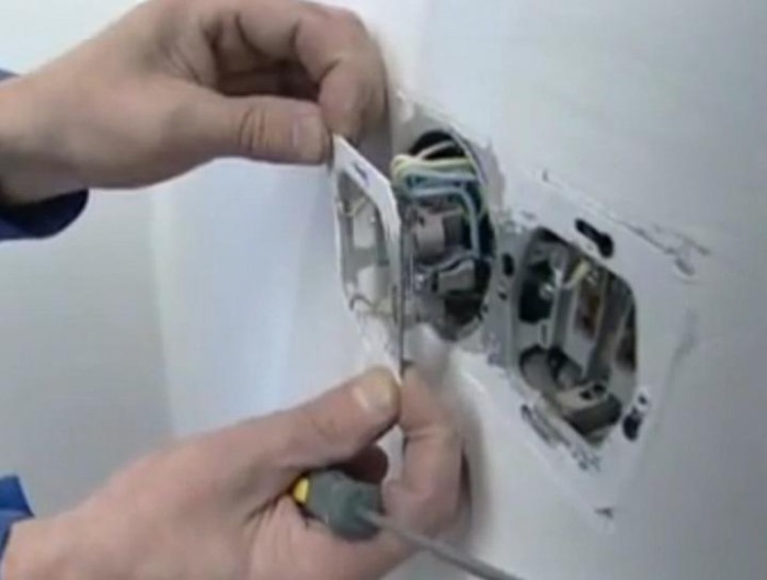
Attention! Despite the variety of switches and sockets, the principle of their installation in the case of open and closed wiring remains the same. Therefore, this manual can be considered universal.
The operation of laying electrical wires in the house is now complete. It remains only to connect electrical appliances and light sources. And comfort and warmth will come to your home.